


OPERATING PRINCIPLES
Rev. B
2-31
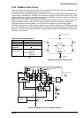
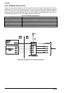
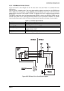
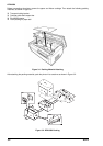
2.3.7 PG Motor Drive Circuit
Figure 2-25 shows a block diagram of the PG motor drive circuit, and Table 2-11 provides PG motor
specifications.
The PG motor is a stepping motor. The motor phase switching signals are output from the E05B36 ports
PGA to PGD. The motor common voltage (PGCOM) alternates between drive mode (+37 VDC) and hold
mode (+5 VDC) using the PG H/R signal of E05B36. The phase driver circuit is made by discrete transistors
Q12 to Q15.
The phase A output pulse from the platen gap encoder (ENCA) is input to port ENCA of E05B36 and the
phase B output pulse from the platen gap encoder (ENCB) is input to port ENCB of E05B36. The E05B36
counts these pulses using the internal counter and determines the amount and direction of motor rotation.
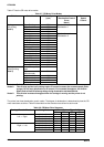
Table 2-11. PG Motor Specifications
Specification Description
Form 4-phase, 48-pole, PM pulse motor
Supply Voltage 37 VDC (applied to the drive circuit)
Internal Coil Resistance 250 + 18 ohms per phase at 25
o
C
Current Consumption Driving: 0.20 A (average)
Holding: 0.02 A + 5 mA
Frequency 285 pps
Driving Method Constant voltage driving, 2-2 phase drive
PG H/R
PG A
PG A
PG B
PG C
PG D
PGENCA
Plsten Gap
Encoder
PG Motor
PGCOM
E05B36
(IC1)
Q12,
Q13,
Q14.
Q15
VP 3
F2
Q10,
Q11
D10
+5V
DRV Board
MAIN Board
PG B
PG C
PG D
PGENCB
Figure 2-25. PG Motor Drive Circuit Block Diagram