MPCMM0001 Chassis Management Module Software Technical Product Specification 33
Built-In Self Test (BIST)
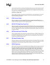
4.2 Boot-BIST
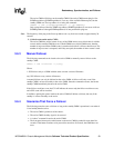
The codes in Boot-BIST are executed at the very early stage of the RedBoot bootstrap, which is
just before the FPGA programming and memory module initialization. Boot-BIST performs
checksum checking over the RedBoot image and the FPGA image. A checksum error will be
detected if there is a mismatch between the calculated checksum and the stored checksum in FIS
directory.
Boot-BIST also performs a Base Memory Test for the first 1 MByte of memory. Whenever there is
an error, BIST will inform the user by prompting a warning message through the console terminal
and log the event to event-log area.
4.3 Early-BIST
The early BIST stage extends the reset timeout period on the watchdog timer (MAX6374) by
strobing GPIO7 on FPGA1. This prevents any possible hardware reset during the BIST process.
The watchdog timer is enabled after the ADM1026 GPIO initialization and disabled once it reaches
the RedBoot console. The OS enables the watchdog timer again and starts the strobing thread at the
kernel level.
4.4 Mid-BIST
This stage of BIST performs the Extended Memory Test to scan and diagnose the possible bit
errors in the memory. It starts scanning from 1 MByte to the 128 MByte. It does not test the
memory below 1 MByte because a portion of RedBoot has already loaded and resided on it.
The memory test includes the walking ones test 32-bit address test, and 32-bit inverse address test.
Furthermore, voltage and temperature ratings will be verified to lie within the hardware tolerable
ranges. The FPGA firmware version is checked and will alert if an older version of an FPGA image
has been detected. Also, system date and time is read from the real-time clock and displayed
through the console terminal. NIC presence is also checked here, though the NIC self-test happens
later when the driver is loaded.
4.5 Late-BIST
Late-BIST disables the watchdog timer once RedBoot is fully loaded. It then verifies the checksum
of the OS image with a stored checksum at the top of flash memory, before proceeding with the
boot script execution.
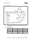
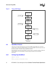
The following diagram shows the times during the boot cycle the when various stages of BIST are
performed.


