


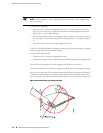
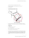

If you must insert the DPC into a bag by yourself, first lay the DPC horizontally on
a flat, stable surface, sheet metal side down. Orient the DPC with the faceplate facing
you. Carefully insert the DPC connector edge into the opening of the bag, and pull
the bag toward you to cover the DPC.
Never stack a DPC under or on top of any other component.
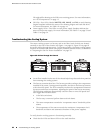
Maintaining the Power Supplies
To maintain the power supplies, follow these guidelines:
■
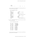
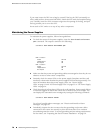
To check the status of the power supplies, issue the show chassis environment
pem command. The output is similar to the following:
user@host> show chassis environment pem
PEM 0 status:
State Online
Temperature OK
DC output OK
PEM 2 status:
State Online
Temperature OK
DC output OK
■ Make sure that the power and grounding cables are arranged so that they do not
obstruct access to other router components.
■ Routinely check the status LEDs on the power supply faceplates and the craft
interface to determine whether the power supplies are functioning normally. For
more information about the power supply LEDs, see “Power Supply
LEDs” on page 19 and “AC Power Supply LEDs” on page 22 or “DC Power Supply
LEDs” on page 24.
■ Check the red and yellow alarm LEDs on the craft interface. Power supply failure
or removal triggers an alarm that causes one or both of the LEDs to light. You
can display the associated error messages by issuing the following command:
user@host> show chassis alarms
For a list of possible alarm messages, see “Chassis and Interface Alarm
Messages” on page 80.
■ Periodically inspect the site to ensure that the grounding and power cables
connected to the router are securely in place and that there is no moisture
accumulating near the router. To review grounding and site wiring requirements
for the router, see “Preparing the Site for Router Installation” on page 29.
78 ■ Maintaining the Power Supplies
MX240 Ethernet Services Router Hardware Guide