


■ Alarm LEDs—One large red circular LED and one large yellow triangular LED,
located on the upper right of the craft interface, indicate two levels of alarm
conditions. The circular red LED lights to indicate a critical condition that can
result in a system shutdown. The triangular yellow LED lights to indicate a less
severe condition that requires monitoring or maintenance. Both LEDs can be lit
simultaneously. A condition that causes an alarm LED to light also activates the
corresponding alarm relay contact on the craft interface.
■
Host subsystem LEDs—Three LEDs, MASTER, ONLINE, and OFFLINE, indicate the
status of the host subsystem. A green MASTER LED indicates that the host is
functioning as the master. The ONLINE LED indicates that the host is online. The
OFFLINE LED indicates that the host is installed but the routing engine is offline.
The host subsystem LEDs are located on the left of the craft interface and are
labeled RE0 and RE1. For more information, see “Host Subsystem
LEDs” on page 19.
■
Power supply LED—Two LEDs (PEM) indicate the status of each power supply.
Green indicates that the power supply is functioning normally. Red indicates
that the power supply is not functioning normally. The power supply LEDs are
located in the center craft interface, and are labeled 0 through 3. For more
information, see “Power Supply LEDs” on page 19.
■
DPC LEDs—Two LEDs, OK and FAIL, indicate the status of each DPC. Green
indicates OK and red indicates a failure. The DPC LEDs are located along the
bottom of the craft interface, and are labeled 0/1, 1, and 2. For more information,
see “DPC LEDs” on page 20.
■
SCB LEDs—Two LEDs, OK and FAIL, indicate the status of each SCB. Green
indicates OK and red indicates a failure. The SCB LEDs are located on the left of
the craft interface along the bottom, and are labeled 0 and 1/0. For more
information, see “SCB LEDs” on page 20.
■
Fan LEDs—Two LEDs indicate the status of the fans. Green indicates OK and red
indicates FAIL. The fan LEDs are located on the upper left of the craft interface.
For more information, see “Host Subsystem LEDs” on page 19.
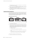
Component LEDs
The following LEDs are located on various router components and display the status
of those components:
■
DPC LED—One LED labeled OK/FAIL on each DPC faceplate indicates the DPC's
status. For more information, see Table 7 on page 10, Table 8 on page 10, and
Table 14 on page 20.
■
SCB LEDs—Three LEDs, labeled FABRIC ACTIVE, FABRIC ONLY, and OK/FAIL, on
each SCB faceplate indicate the status of the SCB. If no LEDs are lit, the master
Overview of Troubleshooting Resources ■ 81
Chapter 12: Troubleshooting Hardware Components