


You enter CLI commands on one or more external management devices connected
to ports on the Routing Engine. For more information about the Routing Engine
ports, see “Routing Engine Interface Ports” on page 16.
For information about using the CLI to display details about alarms generated by
interfaces and hardware components, see “Chassis and Interface Alarm
Messages” on page 80. For information about using the CLI to troubleshoot the JUNOS
software, see the appropriate JUNOS software configuration guide.
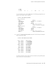
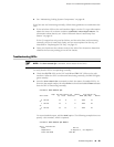
Chassis and Interface Alarm Messages
When the Routing Engine detects an alarm condition, it lights the red or yellow alarm
LED on the craft interface as appropriate. To view a more detailed description of the
alarm cause, issue the show chassis alarms command:
user@host> show chassis alarms
There are two classes of alarm messages:
■ Chassis alarms—Indicate a problem with a chassis component such as the cooling
system or power supplies.
■ Interface alarms—Indicate a problem with a specific network interface.
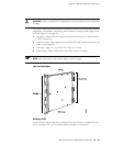
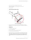
Alarm Relay Contacts
The craft interface has two alarm relay contacts for connecting the router to external
alarm devices (see Figure 14 on page 21). Whenever a system condition triggers
either the red or yellow alarm on the craft interface, the alarm relay contacts are
also activated. The alarm relay contacts are located on the upper right of the craft
interface.
LEDs
LEDs on the router display the status of various components. This section describes
the following types of LEDs:
■ Craft Interface LEDs on page 80
■ Component LEDs on page 81
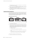
Craft Interface LEDs
The craft interface is the panel on the front of the router located above the DPC cards
that contains LEDs and buttons that allow you to troubleshoot the router (see
Figure 13 on page 18). For more information about the craft interface, see “Craft
Interface” on page 17.
LEDs on the craft interface include the following:
80 ■ Overview of Troubleshooting Resources
MX240 Ethernet Services Router Hardware Guide