


Component Redundancy
The MX240 chassis provides redundancy and resiliency. The hardware system is
fully redundant, including power supplies, Routing Engines, and SCBs.
A fully configured router is designed so that no single point of failure can cause the
entire system to fail. Only a fully configured router provides complete redundancy.
All other configurations provide partial redundancy. The following major hardware
components are redundant:
■ Host subsystem—The host subsystem consists of a Routing Engine functioning
together with an SCB. The router can have one or two host subsystems. If two
host subsystems are installed, one functions as the master and the other functions
as the backup. If the master host subsystem (or either of its components) fails,
the backup can take over as the master. To operate, each host subsystem requires
a Routing Engine installed directly into in an SCB.
If the Routing Engines are configured for nonstop routing and graceful switchover,
the backup Routing Engine automatically synchronizes its configuration and
state with the master Routing Engine. Any update to the master Routing Engine
state is replicated on the backup Routing Engine. If the backup Routing Engine
assumes mastership, packet forwarding continues through the router without
interruption. For more information about nonstop routing and graceful switchover,
see the JUNOS High Availability Configuration Guide.
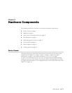
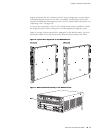
■ In the high-line (220 V) AC power configuration, the MX240 router contains one
or two AC power supplies, located horizontally at the rear of the chassis in slots
PEM0 and PEM2 (left to right) (see Figure 3 on page 7). The high-line
configuration requires one power supply, with the second power supply providing
redundancy. Each AC power supply provides power to all components in the
router. When two power supplies are present, they share power almost equally
within a fully populated system. If one power supply fails or is removed, the
remaining power supply assumes the entire electrical load without interruption.
One power supply can provide the maximum configuration with full power for
as long as the router is operational.
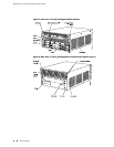
■ In the low-line (110 V) AC power configuration, the MX240 router contains either
two AC power supplies (nonredundant), located horizontally at the rear of the
chassis in slots PEM0 and PEM1 (left to right); or four AC power supplies
(redundant), located in slots PEM0 through PEM3 (left to right) (see
Figure 2 on page 6). The low-line configuration requires two power supplies,
and the third and fourth power supplies provide redundancy. Each AC power
supply provides power to all components in the router. When two power supplies
are present, they share power almost equally within a fully populated system.
If one power supply in a redundant configuration fails or is removed, the
remaining power supplies assume the entire electrical load without interruption.
Two power supplies provide the maximum configuration with full power for as
long as the router is operational.
■ Cooling system—The cooling system has redundant components, which are
controlled by the host subsystem. If one of the fans fails, the host subsystem
increases the speed of the remaining fans to provide sufficient cooling for the
router indefinitely.
4 ■ Component Redundancy
MX240 Ethernet Services Router Hardware Guide