


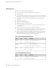
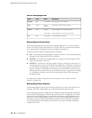
Table 8: 40-Port Gigabit Ethernet DPC LEDs (continued)
DescriptionStateColorLabel
Link is active.
No link.
On steadilyGreen
Off
LINK
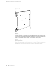
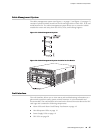
Two LEDs, located on the craft interface above the DPC, display the status of the
DPC and are labeled OK and FAIL. For more information about the DPC LEDs located
on the craft interface, see “DPC LEDs” on page 20.
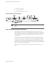
Host Subsystem
The host subsystem provides the routing and system management functions of the
router. You can install one or two host subsystems on the router. Each host subsystem
functions as a unit; the Routing Engine must be installed directly into the Switch
Control Board.
NOTE: We recommend that you install two host subsystems for redundant protection.
If you install only one host subsystem, we recommend that you install it in slot 0.
Each host subsystem has three LEDs that display its status. The host subsystem LEDs
are located on the upper left of the craft interface. For more information about the
host subsystem LEDs, see “Host Subsystem LEDs” on page 19.
The host subsystem consists of the following components:
■ Switch Control Board (SCB) on page 11
■ Routing Engine on page 14
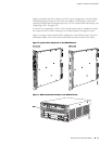
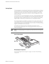
Switch Control Board (SCB)
The Switch Control Board (SCB) provides the following functions:
■ Powers on and powers off DPCs
■ Controls clocking, system resets and booting
■ Monitors and controls system functions, including fan speed, board power status,
PDM status and control, and the craft interface
■ Provides interconnections to all the DPCs within the chassis through the switch
fabrics integrated into the SCB
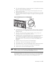
The Routing Engine installs directly into a slot on the SCB (see Figure 8 on page 12).
Host Subsystem ■ 11
Chapter 2: Hardware Components