


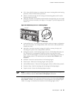
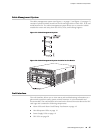
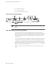

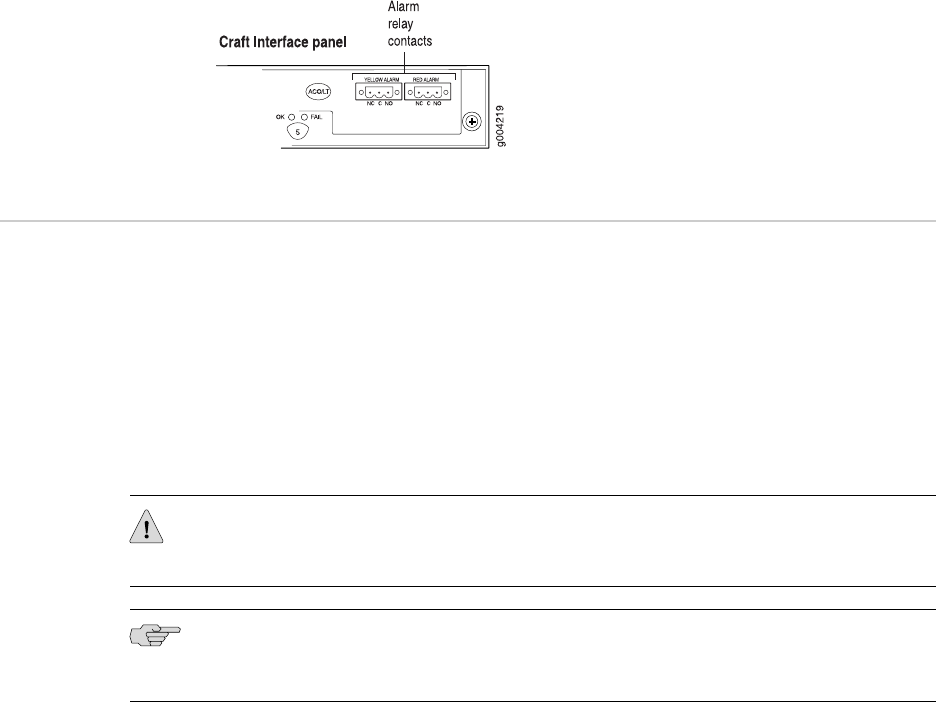
Alarm Relay Contacts
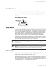
The craft interface has two alarm relay contacts for connecting the router to external
alarm devices (see Figure 14 on page 21). Whenever a system condition triggers
either the red or yellow alarm on the craft interface, the alarm relay contacts are
also activated. The alarm relay contacts are located on the upper right of the craft
interface.
Figure 14: Alarm Relay Contacts
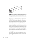
Power Supplies
The MX240 router uses either AC or DC power supplies. You can configure the MX240
router with either one or two high-line (220 V) AC power supplies, two or four low-line
(110 V) AC power supplies, or one or two DC power supplies. The power supplies
connect to the midplane, which distributes the different output voltages produced
by the power supplies to the router components, depending on their voltage
requirements. Each power supply is cooled by its own internal cooling system.
Redundant power supplies are hot-removable and hot-insertable. When you remove
a power supply from a router that uses a nonredundant power supply configuration,
the router might shut down depending on your configuration.
CAUTION: The router cannot be powered from AC and DC power supplies
simultaneously.
NOTE: Routers configured with only one or two power supplies are shipped with a
blank panel installed over the power supply slots that are not populated.
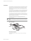
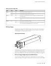
AC Power Supply
Each AC power supply weighs approximately 5.0 lb (2.3 kg) and consists of one AC
appliance inlet, one AC switch, a fan, and LEDs to monitor the status of the power
supply. Figure 15 on page 22 shows the power supply.
Each inlet requires a dedicated AC power feed and a dedicated facility circuit breaker.
We recommend that you use a minimum 15 A (250 VAC) facility circuit breaker, or
as required by local code. For information about connecting the router to power, see
“Connecting Power to an AC-Powered Router” on page 54.
Power Supplies ■ 21
Chapter 2: Hardware Components