


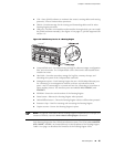
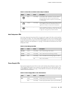
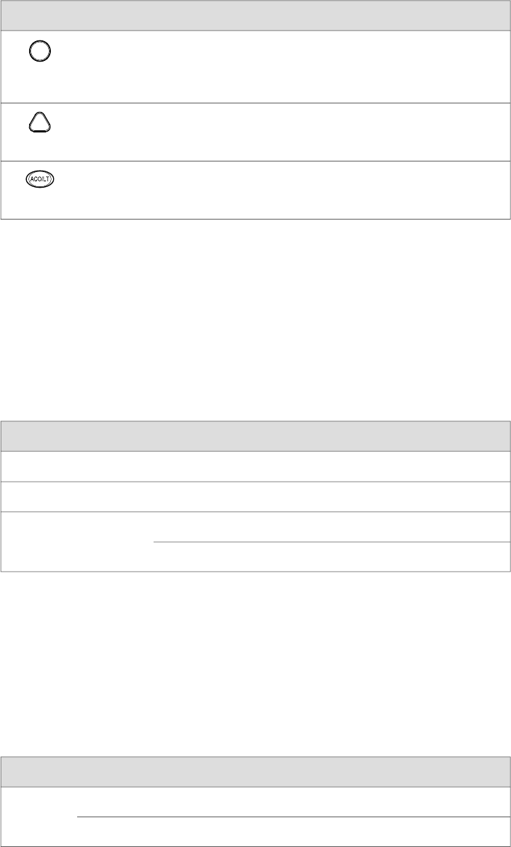
Table 11: Alarm LEDs and Alarm Cutoff/Lamp Test Button
DescriptionStateColorShape
Critical alarm LED—Indicates a critical condition
that can cause the router to stop functioning.
Possible causes include component removal, failure,
or overheating.
On steadilyRed
Warning alarm LED—Indicates a serious but nonfatal
error condition, such as a maintenance alert or a
significant increase in component temperature.
On steadilyYellow
Alarm cutoff/lamp test button—Deactivates red and
yellow alarms. Causes all LEDs on the craft interface
to light (for testing) when pressed and held.
––
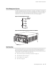
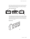
Host Subsystem LEDs
Each host subsystem has three LEDs, located on the upper left of the craft interface,
that indicate its status. The LEDs labeled RE0 show the status of the Routing Engine
in slot 0 and the SCB in slot 0. The LEDs labeled RE1 show the status of the Routing
Engine and SCB in slot 1/0Table 12 on page 19 describes the functions of the host
subsystem LEDs.
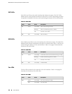
Table 12: Host Subsystem LEDs
DescriptionStateColorLabel
Host is functioning as the master.On steadilyGreen
MASTER
Host is online and is functioning normally.On steadilyGreen
ONLINE
Host is installed but the Routing Engine is offline.On steadilyRed
OFFLINE
Host is not installed.Off
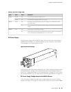
Power Supply LEDs
Each power supply has two LEDs on the craft interface that indicate its status. The
LEDs, labeled 0 through 3, are located on the upper left of the craft interface next
to the PEM label. Table 13 on page 19 describes the functions of the power supply
LEDs on the craft interface.
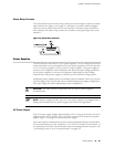
Table 13: Power Supply LEDs on the Craft Interface
DescriptionStateColorLabel
Power supply is functioning normally.On steadilyGreen
PEM
Power supply has failed or power input has failed.On steadilyRed
Craft Interface ■ 19
Chapter 2: Hardware Components