


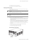


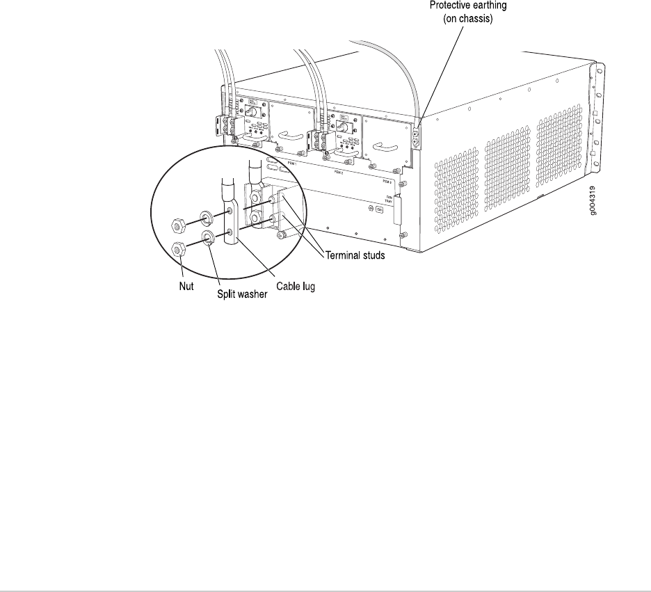
Figure 58: Connecting Power Cables to the DC Power Supply
4. Replace the clear plastic cover over the terminal studs on the faceplate.
5. Verify that the DC power cable is connected correctly, that it does not touch or
block access to router components, and that it does not drape where people
could trip on it.
6. Attach the power cable to the DC power source.
7. Turn on the dedicated facility circuit breaker to the power supply.
8.
Verify that the INPUT OK LED on the power supply is lit green steadily.
9.
Switch the circuit breaker on the power supply to the ON position — and observe
the status LEDs on the power supply faceplate. If the power supply is correctly
installed and functioning normally, the PWR OK, BRKR ON, and INPUT OK LEDs
light green steadily.
Replacing the Cable Management System
■ Removing the Cable Management System on page 121
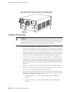
■ Installing the Cable Management System on page 122
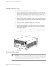
Removing the Cable Management System
The cable management system is located on both sides of the DPC card cage. The
cable management system weighs approximately 0.3 lb (0.14 kg).
To remove the cable management system (see Figure 59 on page 122):
1. Attach an electrostatic discharge (ESD) grounding strap to your bare wrist and
connect the strap to one of the ESD points on the chassis. For more information
about ESD, see “Preventing Electrostatic Discharge Damage” on page 130.
Replacing the Cable Management System ■ 121
Chapter 13: Replacing Hardware Components