


and PEM2 (left to right). You can upgrade your DC power system from one to two
power supplies. A single DC power supply provides power to all components.
One DC power supply is required. A second DC power supply provides redundancy.
If a DC power supply in a redundant configuration fails, the redundant power supply
takes over without interruption.
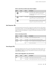
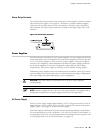
DC Power Supply LEDs
Each DC power supply faceplate contains three LEDs that indicate the status of the
power supply (see Table 18 on page 24). The power supply status is also reflected
in two LEDs on the craft interface (see Table 13 on page 19). In addition, a power
supply failure triggers the red alarm LED on the craft interface.
NOTE: An SCB must be present for the PWR OK LED to go on.
Table 18: DC Power Supply LEDs
DescriptionStateColorLabel
Power supply is not functioning normally. Check the INPUT OK LED for more
information.
OffGreen
PWR OK
Power supply is functioning normally.On
The main output voltage is out of range (lower limit: 37.5 V to 39.5 V; upper limit:
72.5 V to 76 V).
OnAmber
DC power supply circuit breaker is turned off.OffGreen
Green
BRKR ON
DC power input is present and the DC power supply circuit breaker is turned on.On
DC input to the PEM is not present.OffGreen
INPUT OK
DC input is present and is connected in correct polarity.On
DC input is present, but not in valid operating range or connected in reverse
polarity.
OnAmber
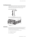
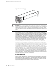
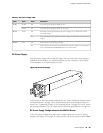
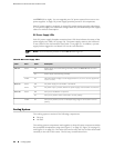
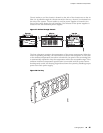
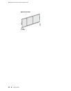
Cooling System
The cooling system consists of the following components:
■ Fan tray
■ Air filter
The cooling system components work together to keep all router components within
the acceptable temperature range (see Figure 17 on page 25, Figure 18 on page 25,
and Figure 19 on page 26). The router has one fan tray and one air filter that install
vertically in the rear of the router. The fan tray contains three fans.
24 ■ Cooling System
MX240 Ethernet Services Router Hardware Guide