


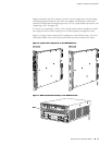
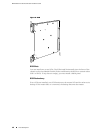
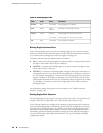

DPC Components
Each DPC consists of the following components:
■ DPC cover, which functions as a ground plane and a stiffener.
■ Fabric interfaces.
■ Two Gigabit Ethernet interfaces that allow control information, route information,
and statistics to be sent between the Routing Engine and the CPU on the DPCs.
■ Two interfaces from the SCBs that enable the DPCs to be powered on and
controlled.
■ Physical DPC connectors.
■ Four Packet Forwarding Engines.
■ Midplane connectors and power circuitry.
■ Processor subsystem, which includes a 1.2-GHz CPU, system controller, and
1 GB of SDRAM.
■ Online button—Takes the DPC online or offline when pressed.
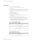
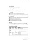
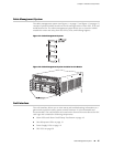
■ LEDs on the 4-port 10-Gigabit Ethernet faceplate, which indicate the port status.
LEDs are labeled top to bottom 0/0 through 0/3 (see Table 7 on page 10).
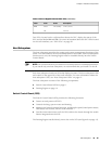
■ LEDs on a 40-port Gigabit Ethernet faceplate indicate the port status. LEDs are
labeled horizontally and left to right 0/0 through 0/5, 1/0 through 1/5, 2/0
through 2/5, and 3/0 through 3/5 (see Table 8 on page 10).
Table 7: Four-Port 10-Gigabit Ethernet DPC LEDs
DescriptionStateColorLabel
DPC is functioning normally.
DPC has failed.
On steadily
On steadily
Green
Red
OK/FAIL
Normal operating mode.
Port configured in tunnel mode.
Off
On steadily
Green
TUNNEL
Link is active.
No link.
On steadily
Off
Green
LINK
Table 8: 40-Port Gigabit Ethernet DPC LEDs
DescriptionStateColorLabel
DPC is functioning normally.
DPC has failed.
On steadily
On steadily
Green
Red
OK/FAIL
10 ■ Dense Port Concentrators (DPCs)
MX240 Ethernet Services Router Hardware Guide