


DC Power Cable Specifications
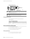
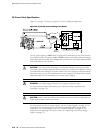
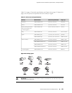
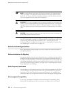
Figure 62 on page 170 shows a typical DC source cabling arrangement.
Figure 62: Typical DC Source Cabling to the Router
The DC power supply in PEM0 must be powered by dedicated power feeds derived
from feed A, and the DC power supply in PEM2 must be powered by dedicated power
feeds derived from feed B. This configuration provides the commonly deployed A/B
feed redundancy for the system.
CAUTION: You must ensure that power connections maintain the proper polarity.
The power source cables might be labeled (+) and (–) to indicate their polarity. There
is no standard color coding for DC power cables. The color coding used by the external
DC power source at your site determines the color coding for the leads on the power
cables that attach to the terminal studs on each power supply.
WARNING: For field-wiring connections, use copper conductors only.
For other electrical safety information, see “Electrical Safety Guidelines and
Warnings” on page 144.
CAUTION: Power cords and cables must not block access to router components or
drape where people could trip on them.
For a description of the DC power supply, see “DC Power Supply” on page 23. For
instructions on connecting the DC power and grounding cables during initial
installation, see “Connecting Power to a DC-Powered Router” on page 56. For
instructions on replacing a DC power cable, see “Replacing a DC Power Supply
Cable” on page 119.
170 ■ DC Power Specifications and Requirements
MX240 Ethernet Services Router Hardware Guide