


■ SCB LEDs on page 20
■ Fan LEDs on page 20
■ Alarm Relay Contacts on page 21
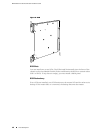
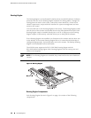
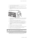
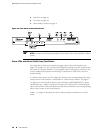
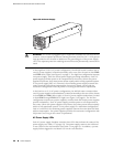
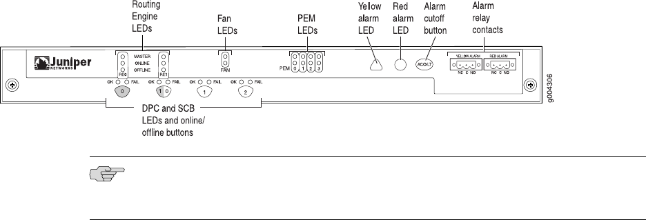
Figure 13: Front Panel of the Craft Interface
NOTE: At least one SCB must be installed in the router for the craft interface to obtain
power.
Alarm LEDs and Alarm Cutoff/Lamp Test Button
Two large alarm LEDs are located at the upper right of the craft interface (see
Figure 13 on page 18). The circular red LED lights to indicate a critical condition that
can result in a system shutdown. The triangular yellow LED lights to indicate a less
severe condition that requires monitoring or maintenance. Both LEDs can be lit
simultaneously.
A condition that causes an LED to light also activates the corresponding alarm relay
contact on the craft interface, as described in “Alarm Relay Contacts” on page 21.
To deactivate red and yellow alarms, press the button labeled ACO/LT (for “alarm
cutoff/lamp test”), which is located to the right of the alarm LEDs. Deactivating an
alarm turns off both LEDs and deactivates the device attached to the corresponding
alarm relay contact on the craft interface.
Table 11 on page 19 describes the alarm LEDs and alarm cutoff button in more
detail.
18 ■ Craft Interface
MX240 Ethernet Services Router Hardware Guide