


Appendix F
Cable Connector Pinouts
This appendix describes the pinouts for the following cable connectors:
■ RJ-45 Connector Pinouts for the Routing Engine ETHERNET Port on page 185
■ RJ-45 Connector Pinouts for the Routing Engine AUX and CONSOLE
Ports on page 185
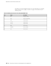
RJ-45 Connector Pinouts for the Routing Engine ETHERNET Port
The port on the craft interface labeled ETHERNET is an autosensing 10/100-Mbps
Ethernet RJ-45 receptacle that accepts an Ethernet cable for connecting the Routing
Engine to a management LAN (or other device that supports out-of-band
management). For more information, see “Routing Engine Interface
Ports” on page 16. Table 40 on page 185 describes the RJ-45 connector pinout.
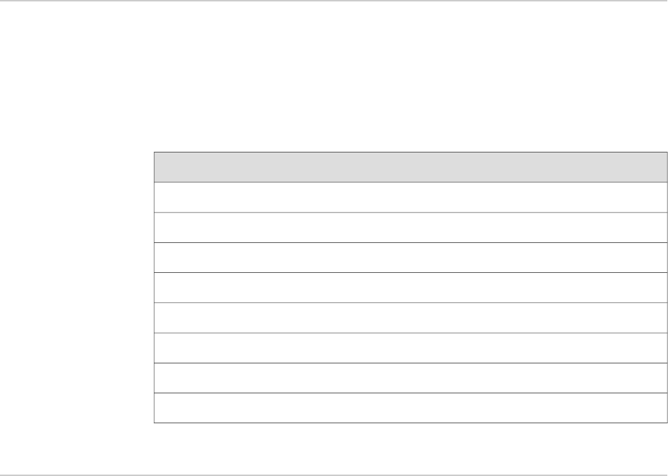
Table 40: RJ-45 Connector Pinout for the Routing Engine ETHERNET Port
SignalPin
TX+1
TX–2
RX+3
Termination network4
Termination network5
RX–6
Termination network7
Termination network8
RJ-45 Connector Pinouts for the Routing Engine AUX and CONSOLE Ports
The ports on the craft interface labeled AUX and CONSOLE are RJ-TGB232 serial
interfaces that accept an RJ-45 connectors. The ports connect the Routing Engine to
RJ-45 Connector Pinouts for the Routing Engine ETHERNET Port ■ 185