


connected to chassis ground at the battery plant, you can use a multimeter to
verify that the ohm output of the –48V and RTN DC cables to chassis ground. .
The cable with very large resistance (indicating an open circuit) to chassis ground
will be –48V and the cable with very low resistance (indicating a closed circuit)
to chassis ground will be RTN.
CAUTION: You must ensure that power connections maintain the proper polarity.
The power source cables might be labeled (+) and (–) to indicate their polarity. There
is no standard color coding for DC power cables. The color coding used by the external
DC power source at your site determines the color coding for the leads on the power
cables that attach to the terminal studs on each power supply.
5. Remove the nuts and washers from the terminal studs. (Use a 3/8-in. nut driver
or socket wrench.)
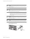
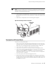
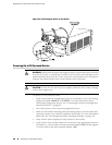
6. Secure each power cable lug to the terminal studs, first with the flat washer, then
with the nut (see Figure 31 on page 58). Apply between 23 lb-in. (2.6 Nm) and
25 lb-in. (2.8 Nm) of torque to each nut. .(Use a 3/8-in. nut driver or socket
wrench.)
■
Secure the positive (+) DC source power cable lug to the RTN (return)
terminal.
■
Secure the negative (–) DC source power cable lug to the –48V (input)
terminal.
NOTE: The DC power supply in PEM0 must be powered by dedicated power feeds
derived from feed A, and the DC power supply in PEM2 must be powered by dedicated
power feeds derived from feed B. This configuration provides the commonly deployed
A/B feed redundancy for the system.
7. Replace the clear plastic cover over the terminal studs on the faceplate.
8. Verify that the power cables are connected correctly, that they are not touching
or blocking access to router components, and that they do not drape where
people could trip on them.
9. If you are installing two power supplies, repeat Steps 2 through 8 for the other
power supply.
Connecting Power to a DC-Powered Router ■ 57
Chapter 9: Grounding and Providing Power to the Router