


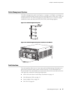
SCB Components
Each SCB consists of the following components:
■ Chassis management Ethernet switch.
■ I2C bus logic, used for low-level communication with each component.
■ Component redundancy circuitry.
■ Control Board/Routing Engine mastership mechanism.
■ Gigabit Ethernet switch that is connected to the embedded CPU complex on all
components.
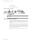
■ Switch fabric—Provides the switching functions for the DPCs.
■ Control FPGA—Provides the Peripheral Component Interconnect (PCI) interface
to the Routing Engine.
■ 1000Base-T Ethernet controller—Provides a 1-Gbps Ethernet link between the
Routing Engines.
■ Ethernet switch—Provides 1-Gbps link speeds between the Routing Engine and
the DPCs.
■ Circuits for chassis management and control.
■ Power circuits for the Routing Engine and SCB.
■ LEDs—Provide status (see “SCB LEDs” on page 13)
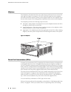
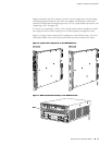
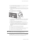
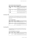
SCB LEDs
Three LEDs on the SCB indicate the status of the SCB. The LEDs, labeled FABRIC
ACTIVE, FABRIC ONLY, and OK/FAIL, are located directly on the SCB. Table 9 on page
13 describes the functions of the SCB LEDs.
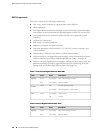
Table 9: Switch Control Board LEDs
DescriptionStateColorLabel
Fabric is in active mode.On steadilyGreen
FABRIC
ACTIVE
SCB operates in fabric-only mode.On steadilyGreen
FABRIC
ONLY
SCB operates in fabric/control board mode.Off
SCB is online.On steadilyGreen
OK/FAIL
SCB is offline.Off
SCB has failed.On steadilyRed
Host Subsystem ■ 13
Chapter 2: Hardware Components