


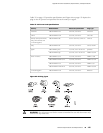

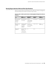


Table 38: Estimated Values for Factors Causing Link Loss (continued)
Estimated Link-Loss ValueLink-Loss Factor
0.5 dBSplice
Single-mode—0.5 dB/km
Multimode—1 dB/km
Fiber attenuation
The following example uses the estimated values in Table 38 on page 181 to calculate
link loss (LL) for a 2 km-long multimode link with a power budget (P
B
) of 13 dB:
■ Fiber attenuation for 2 km @ 1.0 dB/km= 2 dB
■ Loss for five connectors @ 0.5 dB per connector = 5(0.5 dB) = 2.5 dB
■ Loss for two splices @ 0.5 dB per splice =2(0.5 dB) = 1 dB
■ Higher-order loss = 0.5 dB
■ Clock recovery module = 1 dB
The power margin (P
M
) is calculated as follows:
P
M
= P
B
– LL
P
M
= 13 dB – 2 km (1.0 dB/km) – 5 (0.5 dB) – 2 (0.5 dB) – 0.5 dB [HOL] – 1 dB [CRM]
P
M
= 13 dB – 2 dB – 2.5 dB – 1 dB – 0.5 dB – 1 dB
P
M
= 6 dB
The following sample calculation for an 8 km-long single-mode link with a power
budget (P
B
) of 13 dB uses the estimated values from Table 38 on page 181 to calculate
link loss (LL) as the sum of fiber attenuation (8 km @ 0.5 dB/km, or 4 dB) and loss
for seven connectors (0.5 dB per connector, or 3.5 dB). The power margin (P
M
) is
calculated as follows:
P
M
= P
B
– LL
P
M
= 13 dB – 8 km (0.5 dB/km) – 7 (0.5 dB)
P
M
= 13 dB – 4 dB – 3.5 dB
P
M
= 5.5 dB
In both examples, the calculated power margin is greater than zero, indicating that
the link has sufficient power for transmission and does not exceed the maximum
receiver input power.
182 ■ Network Cable Specifications and Guidelines
MX240 Ethernet Services Router Hardware Guide