


CAUTION: You must ensure that power connections maintain the proper polarity.
The power source cables might be labeled (+) and (–) to indicate their polarity. There
is no standard color coding for DC power cables. The color coding used by the external
DC power source at your site determines the color coding for the leads on the power
cables that attach to the terminal studs on each power supply.
NOTE: For the MX240 router, the DC power supply in PEM0 must be powered by
dedicated power feeds derived from feed A, and the DC power supply in PEM2 must
be powered by dedicated power feeds derived from feed B. This configuration
provides the commonly deployed A/B feed redundancy for the system.
NOTE: For information about connecting to DC power sources, see “DC Power
System Electrical Specifications” on page 167.
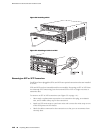
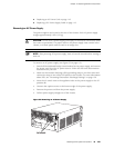
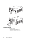
9. Replace the clear plastic cover over the terminal studs on the faceplate.
10. Verify that the power cabling is correct, that the cables are not touching or
blocking access to router components, and that they do not drape where people
could trip on them.
11.
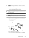
Verify that the INPUT OK LED on the power supply is lit green.
12.
Switch the circuit breaker on the power supply to the ON position — and observe
the status LEDs on the power supply faceplate. If the power supply is correctly
installed and functioning normally, the PWR OK, BRKR ON, and INPUT OK LEDs
light green steadily.
NOTE: If more than one power supply is being installed, turn on all power supplies
at the same time.
NOTE: An SCB must be present for the PWR OK LED to go on.
Replacing Power System Components ■ 117
Chapter 13: Replacing Hardware Components