


Connecting the Alarm Relay Wires
To connect the alarm relay wires between a router and an alarm-reporting device
(see Figure 38 on page 91):
1. Prepare the required length of replacement wire with gauge between 28-AWG
and 14-AWG (0.08 and 2.08 mm
2
).
2. Insert the replacement wires into the slots in the front of the block. Use a 2.5-mm
flat-blade screwdriver to tighten the screws and secure the wire.
3. Plug the terminal block into the relay contact, and use a 2.5-mm flat-blade
screwdriver to tighten the screws on the face of the block.
4. Attach the other end of the wires to the external device.
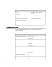
Replacing Cooling System Components
■ Replacing the Fan Tray on page 92
■ Replacing the Air Filter on page 94
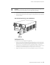
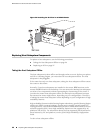
Replacing the Fan Tray
The router has one fan tray that installs vertically in the rear of the chassis. The fan
tray contains three fans. The fan tray is hot-removable and hot-insertable.
The fan tray is located in the rear of the chassis on the right side. The fan tray weighs
about 4.2 lb (1.9 kg).
NOTE: To prevent overheating, install the replacement fan tray immediately after
removing the existing fan tray.
To replace the fan tray, use the following procedures:
■ Removing the Fan Tray on page 92
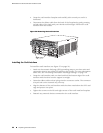
■ Installing the Fan Tray on page 93
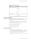
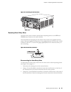
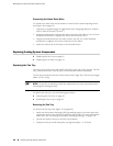
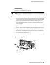
Removing the Fan Tray
To remove the fan tray (see Figure 39 on page 93):
1. Attach an electrostatic discharge (ESD) grounding strap to your bare wrist and
connect the strap to one of the ESD points on the chassis. For more information
about ESD, see “Preventing Electrostatic Discharge Damage” on page 130.
2. Loosen the captive screws on the fan tray faceplate.
3. Grasp the fan tray handle and pull it out approximately 1 to 3 inches.
92 ■ Replacing Cooling System Components
MX240 Ethernet Services Router Hardware Guide