


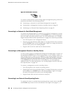
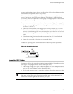
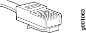
Figure 27: RJ-45 Cable Connector
To connect external devices to the Routing Engine management ports, perform the
procedures described in the following sections:
■ Connecting to a Network for Out-of-Band Management on page 50
■ Connecting to a Management Console or Auxiliary Device on page 50
■ Connecting to an External Alarm-Reporting Device on page 50
Connecting to a Network for Out-of-Band Management
To connect the Routing Engine to a network for out-of-band management, connect
an Ethernet cable with RJ-45 connectors to the ETHERNET port on the Routing Engine.
One such cable is provided with the router. For cable specifications, see “Routing
Engine Interface Cable and Wire Specifications” on page 183. Follow this procedure:
1. Turn off the power to the management device.
2. Plug one end of the Ethernet cable (Figure 27 on page 50 shows the connector)
into the ETHERNET port on the Routing Engine. Figure 26 on page 49 shows the
external device ports on the Routing Engine.
3. Plug the other end of the cable into the network device.
Connecting to a Management Console or Auxiliary Device
To use a system console to configure and manage the Routing Engine, connect it to
the appropriate CONSOLE port on the Routing Engine. To use a laptop, modem, or
other auxiliary device, connect it to the AUX port on the Routing Engine. Both ports
accept a cable with an RJ-45 connector. One serial cable with an RJ-45 connector
and a DB-9 connector is provided with the router. If you want to connect a device
to the CONSOLE port and another device to the AUX port, you must supply an
additional cable. For cable specifications, see “Routing Engine Interface Cable and
Wire Specifications” on page 183.
To connect a management console or auxiliary device:
1. Turn off the power to the console or auxiliary device.
2. Plug the RJ-45 end of the serial cable (Figure 27 on page 50 shows the connector)
into the AUX port or CONSOLE port on the Routing Engine. Figure 26 on page
49 shows the external device ports on the Routing Engine.
3. Plug the female DB-9 end into the device's serial port.
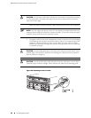
Connecting to an External Alarm-Reporting Device
To connect the router to external alarm-reporting devices, attach wires to the RED
and YELLOW relay contacts on the craft interface. (See Figure 28 on page 51.) A
50 ■ Connecting the Router to Management and Alarm Devices
MX240 Ethernet Services Router Hardware Guide