


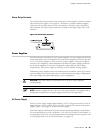
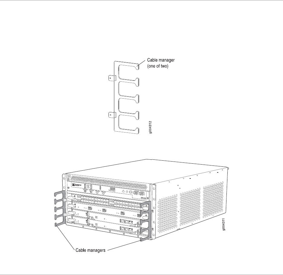
Cable Management System
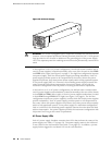
The cable management system (see Figure 11 on page 17 and Figure 12 on page 17)
consists of plastic dividers located on the left and right sides of each DPC, SCB, and
multifunction slot. The cable management system allows you to route the cables
outside the router and away from the DPCs, SCBs, and Routing Engines.
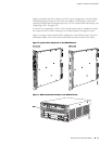
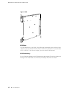
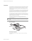
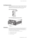
Figure 11: Cable Management System
Figure 12: Cable Management System Installed on the Router
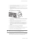
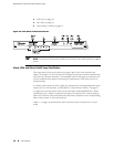
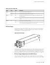
Craft Interface
The craft interface allows you to view status and troubleshooting information at a
glance and to perform many system control functions. It is hot-insertable and
hot-removable. The craft interface is located on the front of the router above the DPC
card cage and contains the following components:
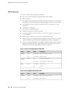
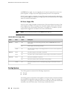
■ Alarm LEDs and Alarm Cutoff/Lamp Test Button on page 18
■ Host Subsystem LEDs on page 19
■ Power Supply LEDs on page 19
■ DPC LEDs on page 20
Cable Management System ■ 17
Chapter 2: Hardware Components