


system condition that triggers the red or yellow alarm LED on the craft interface also
activates the corresponding alarm relay contact.
The terminal blocks that plug into the alarm relay contacts are supplied with the
router. They accept wire of any gauge between 28-AWG and 14-AWG (0.08 and
2.08 mm
2
), which is not provided. Use the gauge of wire appropriate for the external
device you are connecting.
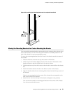
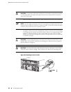
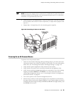
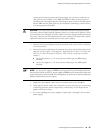
To connect an external device to an alarm relay contact (see Figure 28 on page 51):
1. Prepare the required length of wire with gauge between 28-AWG and 14-AWG
(0.08 and 2.08 mm
2
).
2. While the terminal block is not plugged into the relay contact, use a 2.5-mm
flat-blade screwdriver to loosen the small screws on its side. With the small
screws on its side facing left, insert wires into the slots in the front of the block
based on the wiring for the external device. Tighten the screws to secure the
wire.
3. Plug the terminal block into the relay contact, and use a 2.5-mm flat-blade
screwdriver to tighten the screws on the face of the block.
4. Attach the other end of the wires to the external device.
To attach a reporting device for the other kind of alarm, repeat the procedure.
Figure 28: Alarm Relay Contacts
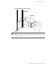
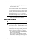
Connecting DPC Cables
Connect the DPCs to the network by plugging in network cables. Follow this procedure
(see Figure 29 on page 52, which shows a fiber-optic DPC):
1. Have ready a length of the type of cable used by the DPC. For cable specifications,
see the MX-series Ethernet Services Router DPC Guide.
2. If the cable connector port is covered by a rubber safety plug, remove the plug.
WARNING: Do not look directly into a fiber-optic transceiver or into the ends of
fiber-optic cables. Fiber-optic transceivers and fiber-optic cable connected to a
transceiver emit laser light that can damage your eyes.
Connecting DPC Cables ■ 51
Chapter 8: Connecting the Router