


5 - 16
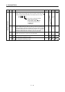
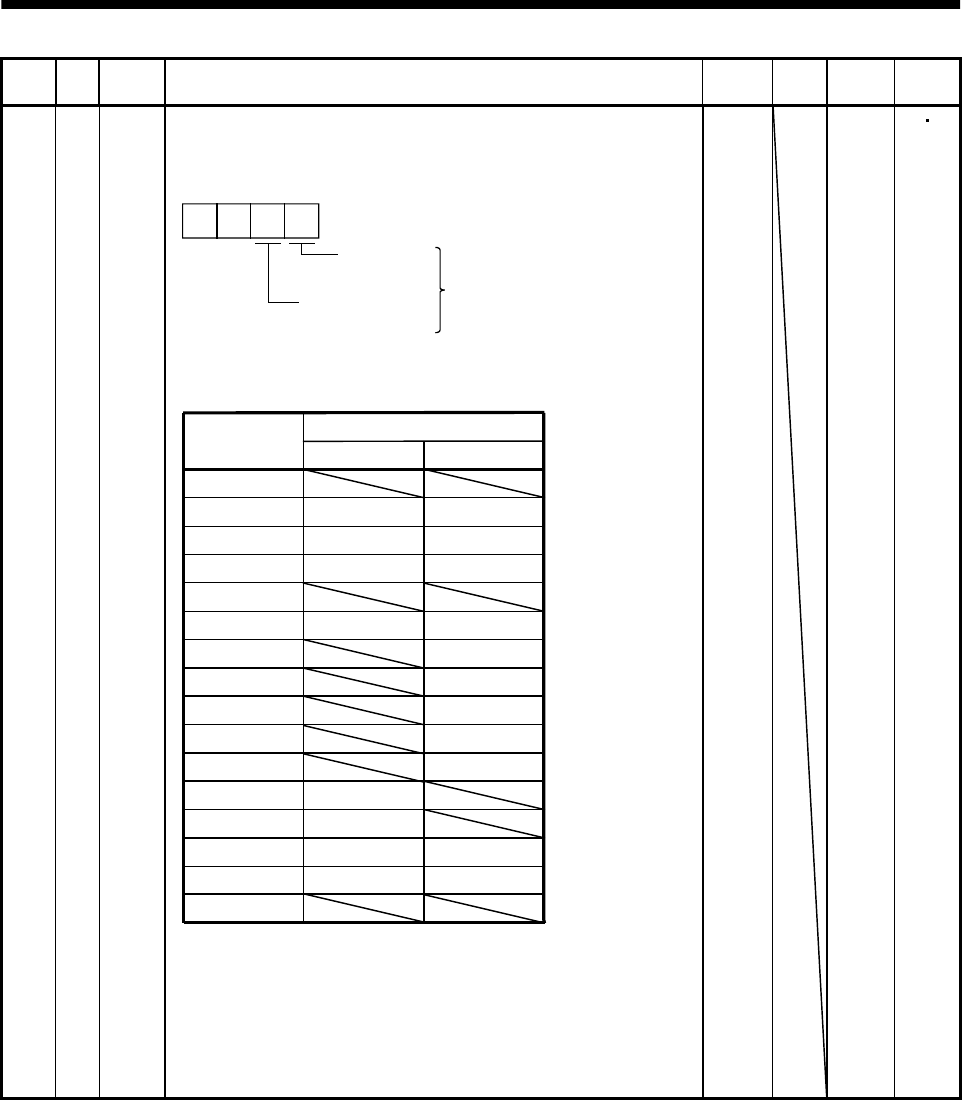
5. PARAMETERS
Class No. Symbol Name and function
Initial
value
Unit
Setting
range
Control
mode
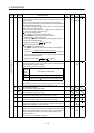
Expansion parameters 1
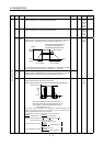
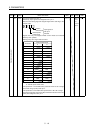
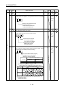
43 *DI2 Input signal selection 2 (CN1-4)
Allows any input signal to be assigned to CN1-pin 4.
Note that the setting digit and assigned signal differ according to the
control mode.
Position
control mode
Input signals of
CN1-pin 4
selected.
Internal speed
control mode
0 0
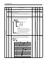
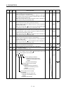
Signals that may be assigned in each control mode are indicated
below by their symbols.
Setting of any other signal will be invalid.
Set value
(Note) Control mode
PS
0
1
2
3
4
5
6
7
8
9
SON SON
RES RES
PC PC
SP1
SP2
ST1
ST2
CR CR
A
SP3
B
C
D
TL1
E
CDP
CM1
CM2
TL1
CDP
F
Note: P: Position control mode
S: Internal speed control mode
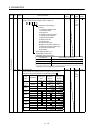
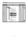
This parameter is unavailable when parameter No.42 is set to assign
the control change (LOP) to CN1-pin 4.
This parameter is unavailable when parameter No. 48 is set to assign
the Forward rotation stroke end (LSP) and Reverse rotation stroke end
(LSN) to be assigned to CN1-pin 4.
0111
Refer to
Name
and
function
column.
P S