15 - 36
15. MR-E-
AG SERVO AMPLIFIER COMPATIBLE WITH ANALOG INPUT
Class No. Symbol Name and function
Initial
value
Unit
Setting
range
Control
mode
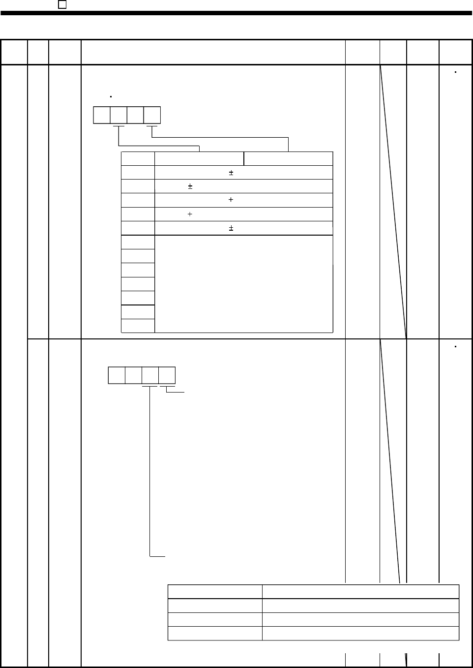
17 MOD Analog monitor output
Used to selection the signal provided to the analog monitor
(MO1)
analog monitor (MO2) output. (Refer to Section 5.2.2)
Setting
0
Analog monitor 2 (MO2)
Servo motor speed ( 8V/max. speed)
1 Torque ( 8V/max. torque)
2 Servo motor speed ( 8V/max. speed)
3 Torque ( 8V/max. torque)
4 Current command ( 8V/max. current command)
5
6
7
8
9
A
00
B
Analog monitor 1 (MO1)
Cannot be used.
0100
Refer to
Name
and
function
column.
S T
18 *
DMD
Status display selection
Used to select the status display shown at power-on.
Selection of status display at
power-on
0: Cumulative feedback pulses
1: Servo motor speed
2: Cannot be used
3: Cannot be used
4: Cannot be used
7: Regenerative load ratio
8: Effective load ratio
9: Peak load ratio
A: Instantaneous torque
B: Within one-revolution position low
C: Within one-revolution position high
D: Load inertia moment ratio
E: Bus voltage
Status display at power-on in
corresponding control mode
0: Depends on the control mode.
0 0
0000
Refer to
Name
and
function
column.
S T
Control Mode
Speed
Speed/torque
Torque
Status display at power-on
Servo motor speed
Servo motor speed/analog torque command voltage
A
nalog torque command voltage
1: Depends on the first digit setting of this parameter.
Basic parameters


