


2 - 2
2. INSTALLATION
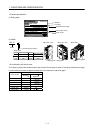
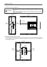
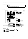
2.2 Installation direction and clearances
CAUTION
The equipment must be installed in the specified direction. Otherwise, a fault may
occur.
Leave specified clearances between the servo amplifier and control box inside
walls or other equipment.
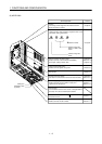
(1) Installation of one servo amplifier
MODE
CN3
SET
CN1
CN2
CNP2
CNP1
L3 L2L1DCP WVU
CHARGE
MITSUBISHI
MR-
Control box Control box
10mm
(0.4 in.)
or more
10mm
(0.4 in.)
or more
40mm
(1.6 in.)
or more
Servo
amplifier
40mm
(1.6 in.)
or more
Wiring clearance
Top
Bottom
(2.8 in.)
70mm
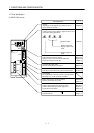
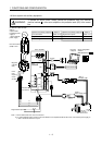
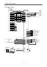
(2) Installation of two or more servo amplifiers
Leave a large clearance between the top of the servo amplifier and the internal surface of the control
box, and install a fan to prevent the internal temperature of the control box from exceeding the
environmental conditions.
MODE
CN3
SET
CN1
CN2
CNP2
CNP1
L3 L2L1DCP WVU
CHARGE
MITSUBISHI
MR-
MODE
CN3
CN1
CN2
CNP2
CNP1
L3 L2L1DCP WVU
CHARGE
MITSUBISHI
MR-
SET
Control box
30mm
(1.2 in.)
or more
30mm
(1.2 in.)
or more
10mm
(0.4 in.)
or more
40mm
(1.6 in.)
or more
100mm
(4.0 in.)
or more