


1 - 5
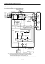
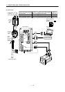
1. FUNCTIONS AND CONFIGURATION
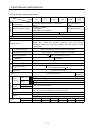
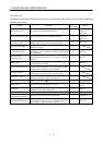
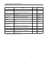
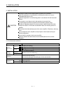
Function Description
(Note)
Control mode
Refer to
Alarm history clear Alarm history is cleared. P, S Parameter No. 16
Restart after instantaneous
power failure
If the input power supply voltage had reduced to cause an
alarm but has returned to normal, the servo motor can be
restarted by merely switching on the start signal.
S Parameter No. 20
Command pulse selection
Command pulse train form can be selected from among four
different types.
P Parameter No. 21
Input signal selection
Forward rotation start, reverse rotation start, servo-on and
other input signals can be assigned to any pins.
P, S
Parameters
No. 43 to 48
Torque limit Servo motor torque can be limited to any value. P, S
Section 3.4.1 (5)
Parameter No. 28
Status display
Servo status is shown on the 5-digit, 7-segment LED
display
P, S Section 6.2
External I/O signal display
ON/OFF statuses of external I/O signals are shown on the
display.
P, S Section 6.6
Output signal (DO)
forced output
Output signal can be forced on/off independently of the
servo status.
Use this function for output signal wiring check, etc.
P, S Section 6.7
Test operation mode
Servo motor can be run from the operation section of the
servo amplifier without the start signal entered.
P, S Section 6.8
Analog monitor output Servo status is output in terms of voltage in real time. P, S Parameter No. 17
Servo configuration software
Using a personal computer, parameter setting, test
operation, status display, etc. can be performed.
P, S Section 13.1.8
Alarm code output
If an alarm has occurred, the corresponding alarm number
is output in 3-bit code.
P, S Section 10.2.1
Note:P: Position control mode, S: Internal speed control mode
P/S: Position/internal speed control change mode