


15 - 2
15. MR-E-
AG SERVO AMPLIFIER COMPATIBLE WITH ANALOG INPUT
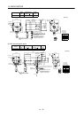
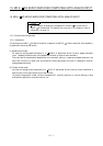
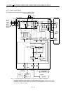
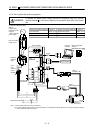
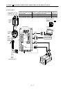
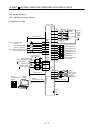
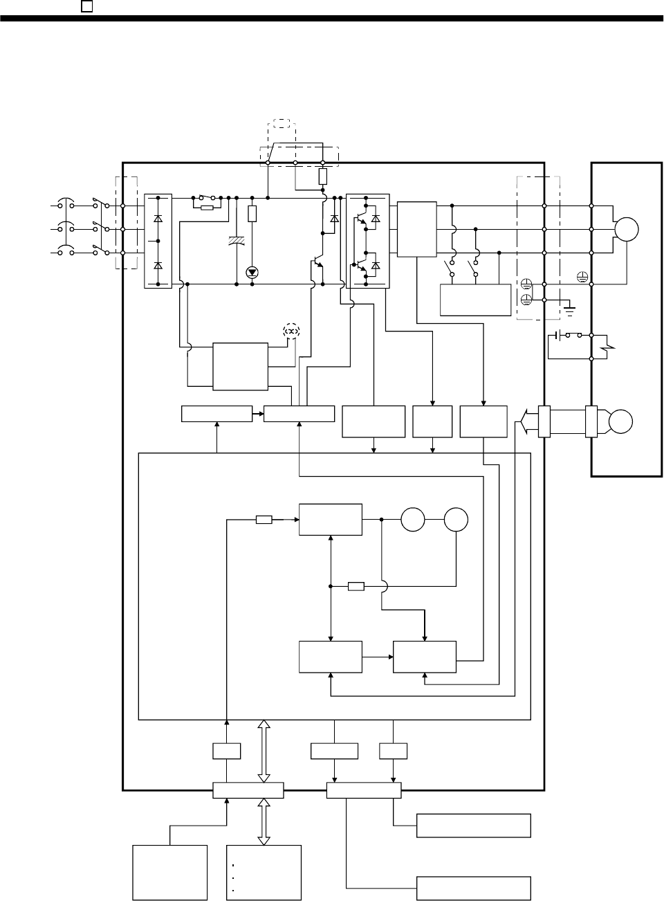
15.1.2 Function block diagram
The function block diagram of this servo is shown below.
(Note 3)
(Note 3)
Regenerative
brake
Base amplifier
Voltage
detection
Over-
current
protection
Detector
Dynamic brake
Current
detector
Regenerative
TR
CHARGE
lamp
RADS
Control
power
supply
Electro-
magnetic
brake
Servo motor
D
C
P
Regenerative brake option
NFB
(Note 2)
Power
s
upply
3
-phase
2
00 to
2
30VAC
S
ingle-phase
2
30VAC
MC
L
1
L
2
L
3
CN1 CN3
RS-232C
Controller
E2
I/F
Servo amplifier
Analog monitor
(2 channels)
Current
detection
Model
speed control
Actual speed
control
Current
control
Model
speed
Model torque
Virtual
motor
Virtual
encoder
CN2
U
V
W
U
V
W
SM
E1
(Note 1)
Fan
(MR-E-200AG only)
RS-232C D/A
(Note 3)
(Note 3)(Note 3)
A/D
Analog
(2 channels)
(Note3)
D I/O control
Servo On
Start
Failure, etc.
Note: 1. The built-in regenerative brake resistor is not provided for the MR-E-10AG/20AG.
2. Single-phase 230VAC power supply can be used for MR-E-70AG or servo amplifiers with smaller
capacities. Connect the power cables to L
1
and L
2
while leaving L
3
open.
3. The control circuit connectors (CN1, CN2 and CN3) are safely isolated from main circuit terminals
(
L
1
,
L
2
,
L
3
,
U
,
V
,
W
,
P
,
C and D
)
.