


3 - 4
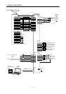
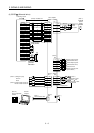
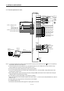
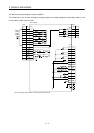
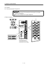
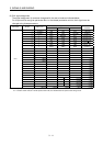
3. SIGNALS AND WIRING
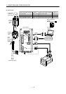
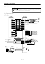
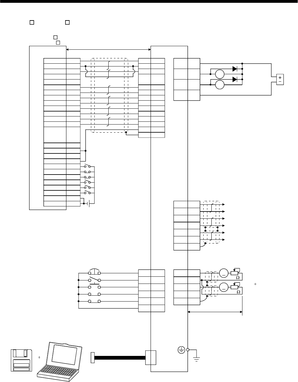
(2) AD75P (A1SD75P )
26
8
24
5
21
4
22
7
23
3
25
6
1
20
12
14
35
16
13
15
11
2
36
19
VIN
INP
LZ
CR
PG
NP
NG
RD
SG
PP
LZR
SD
LG
DOG
COM
RLS
START
CHG
FLS
STOP
COM
READY
COM
INPS
CLEAR
PGO(24V)
PGO(5V)
PGO COM
CLEAR COM
PULSE F-
PULSE F+
PULSE R-
PULSE R+
PULSE F
PULSE COM
PULSE R
PULSE COM
17
16
18
LA
LAR
LB
LBR
SD
15
4
3
SD
6
MO1
LG
MO2
A
A
CN3
21
14
LG
OP
8
4
3
6
7
13
EMG
SON
RES
LSP
LSN
SG
CN1
CN3
CN1
CN1
9
12
RA1
RA2
ALM
ZSP
1VIN
CN1
13 SG
11
1
10
19
20
5
13
22
23
24
25
14
(Note 8)
24VDC
Positioning module
AD75P
(A1SD75P )
(Note 9) 10m(32ft) max.
Servo amplifier
(Note 2, 4)
(Note 6)
Trouble
Zero speed
Encoder A-phase pulse
(differential line driver)
Encoder B-phase pulse
(differential line driver)
Control common
Encoder Z-phase pulse
(open collector)
(Note 3, 5) Emergency stop
Servo-on
Reset
(Note 5) Forward rotation stroke end
Reverse rotation stroke end
(Note 10)
Servo configuration
software
Personal
computer
(Note 7)
Communication cable
(Note 1)
(Note 7)
Monitor output
Max. 1mA
Reading in both
directions
2m(6.5ft) max.
(Note 11)
10k
10k
(Note 8)
(Note 8)
(Note 8)
(Note 8)
(Note 8)
Plate
Plate
Plate
External
power
supply
24VDC
(Note 12)