


15 - 42
15. MR-E-
AG SERVO AMPLIFIER COMPATIBLE WITH ANALOG INPUT
Class No. Symbol Name and function
Initial
value
Unit
Setting
range
Control
mode
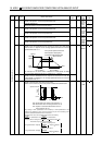
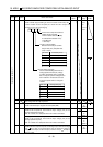
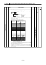
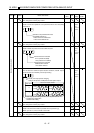
S T41 *DIA Input signal automatic ON selection
Used to set automatic servo-on (SON)
forward rotation stroke end
(LSP)
reverse rotation stroke end (LSN).
Servo-on (SON) input selection
0: Switched on/off by external input.
1: Switched on automatically in servo
amplifier.
(No need of external wiring)
0: Switched on/off by external input.
1: Switched on automatically in servo
amplifier.
(No need of external wiring)
0: Switched on/off by external input.
1: Switched on automatically in servo
amplifier.
(No need of external wiring)
Reverse rotation stroke end (LSN)
input selection
Forward rotation stroke end (LSP)
input selection
0
0000
Refer to
Name
and
function
column.
S
S/T
Expansion parameters 1
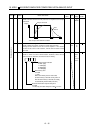
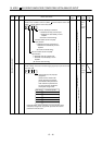
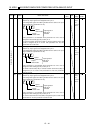
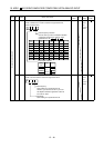
42 *DI1 Input signal selection 1
Used to assign the control mode changing signal input pins and to set
the clear (CR).
Control change (LOP) input pin
assignment
Used to set the control mode
change signal input connector
pins. Note that this parameter is
made valid when parameter No.
0 is set to select the position/int-
ernal speed change mode.
Set value
0
1
2
Connector pin No.
CN1-4
CN1-3
CN1-5
3CN1-6
4CN1-7
0 00
If forward rotation stroke end (LSP) or reverse rotation stroke
end (LSN) is assigned to any pin with parameter No. 48, this
parameter cannot be used.
0002
Refer to
Name
and
function
column.