


15 - 55
15. MR-E-
AG SERVO AMPLIFIER COMPATIBLE WITH ANALOG INPUT
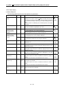
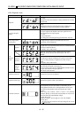
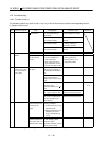
15.5.3 Diagnostic mode
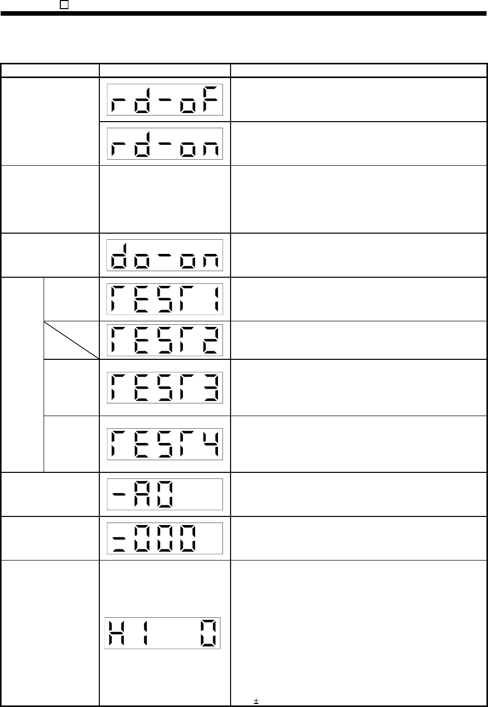
Name Display Description
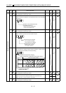
Not ready.
Indicates that the servo amplifier is being initialized or an alarm
has occurred.
Sequence
Ready.
Indicates that the servo was switched on after completion of
initialization and the servo amplifier is ready to operate.
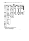
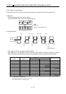
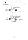
External I/O signal
display
Refer to section 15.5.4.
Indicates the ON-OFF states of the external I/O signals.
The upper segments correspond to the input signals and the
lower segments to the output signals.
Lit: ON
Extinguished: OFF
The I/O signals can be changed using parameters No. 43 to 49.
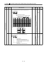
Output signal (DO)
forced output
The digital output signal can be forced on/off. For more
information, refer to section 6.7.
Jog feed
Jog operation can be performed when there is no command from
the external command device.
For details, refer to section 6.8.2.
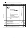
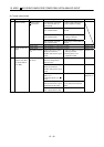
Screen for manufacturer setting. When this screen is being
displayed, do not press any other buttons than "
UP
" and
"
DOWN
".
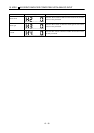
Motorless
operation
Without connection of the servo motor, the servo amplifier
provides output signals and displays the status as if the servo
motor is running actually in response to the external input
signal.
For details, refer to section 6.8.4.
Test
operation
mode
Machine
analyzer
operation
Merely connecting the servo amplifier allows the resonance point
of the mechanical system to be measured.
The servo configuration software (MRZJW3-SETUP154E or later)
is required for machine analyzer operation.
Gain search cannot be used.
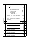
Software version low Indicates the version of the software.
Software version high Indicates the system number of the software.
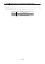
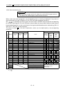
Automatic VC offset
If offset voltages in the analog circuits inside and outside the
servo amplifier cause the servo motor to rotate slowly at the
analog speed command (VC) or analog speed limit (VLA) of 0V,
this function automatically makes zero-adjustment of offset
voltages.
When using this function, make it valid in the following
procedure. Making it valid causes the parameter No. 29 value to
be the automatically adjusted offset voltage.
1) Press "SET" once.
2) Set the number in the first digit to 1 with "UP"/"DOWN".
3) Press "SET".
You cannot use this function if the input voltage of VC or VLA
is
0.4V or more.