5 - 19
5. PARAMETERS
Class No. Symbol Name and function
Initial
value
Unit
Setting
range
Control
mode
Expansion parameters 1
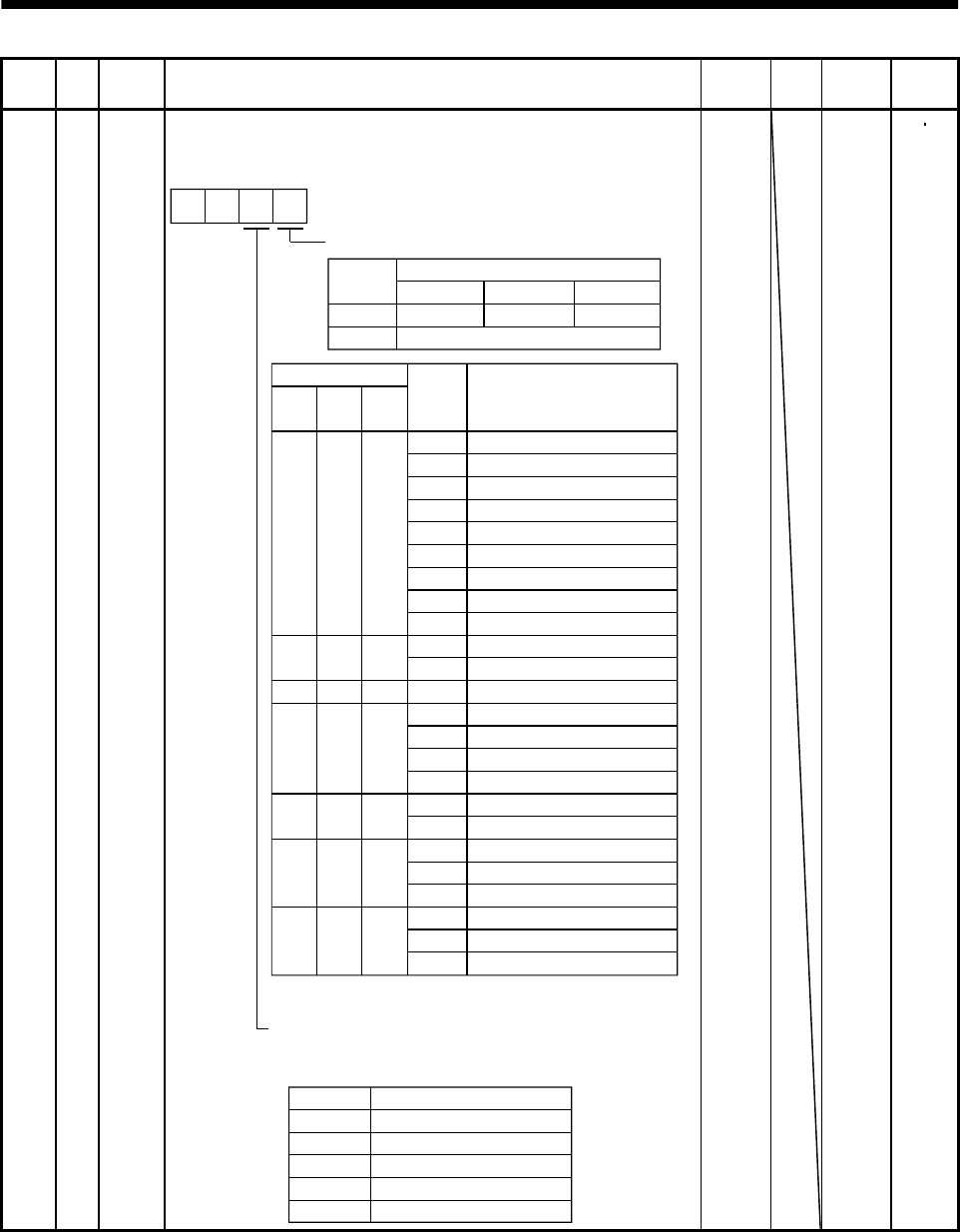
49 *DO1 Output signal selection 1
Used to select the connector pins to output the alarm code and
warning (WNG).
Setting of alarm code output
Connector pins
Set value
CN1-10
CN1-11
CN1-12
0INP or SA
RD
ZSP
1
88888
AL.12
AL.13
AL.15
AL.17
AL.8A
AL.8E
AL.30
AL.45
AL.50
AL.51
AL.24
AL.32
AL.31
AL.35
AL.52
AL.16
AL.20
Name
Watchdog
Memory error 1
Clock error
Memory error 2
Board error 2
Serial communication time-out error
Serial communication error
Regenerative error
Main circuit device overheat
Overload 1
Overload 2
Main circuit
Overcurrent
Overspeed
Command pulse frequency error
Error excessive
Encoder error 1
Encoder error 2
Alarm
display
(Note) Alarm code
CN1
pin 10
0
0
0
0
1
CN1
pin 11
0
0
1
1
0
1
CN1
pin 12
1
1
0
1
0
10
Set value Connector pin No.
Note: 0:off
1:on
Setting of warning (WNG) output
Select the connector pin to output warning. The old signal
before selection will be unavailable.
AL.19
Memory error 3
AL.37 Parameter error
AL.33 Overvoltage
AL.46 Servo motor overheat
AL.10 Undervoltage
1
0
0
AL.1A
Motor combination error
0 Not output.
1CN1-11
2CN1-9
3CN1-10
4CN1-12
0
Alarm code is output at alarm occurrence.
0
0000
Refer to
Name
and
function
column.
P S


