15 - 33
15. MR-E-
AG SERVO AMPLIFIER COMPATIBLE WITH ANALOG INPUT
Class No. Symbol Name and function
Initial
value
Unit
Setting
range
Control
mode
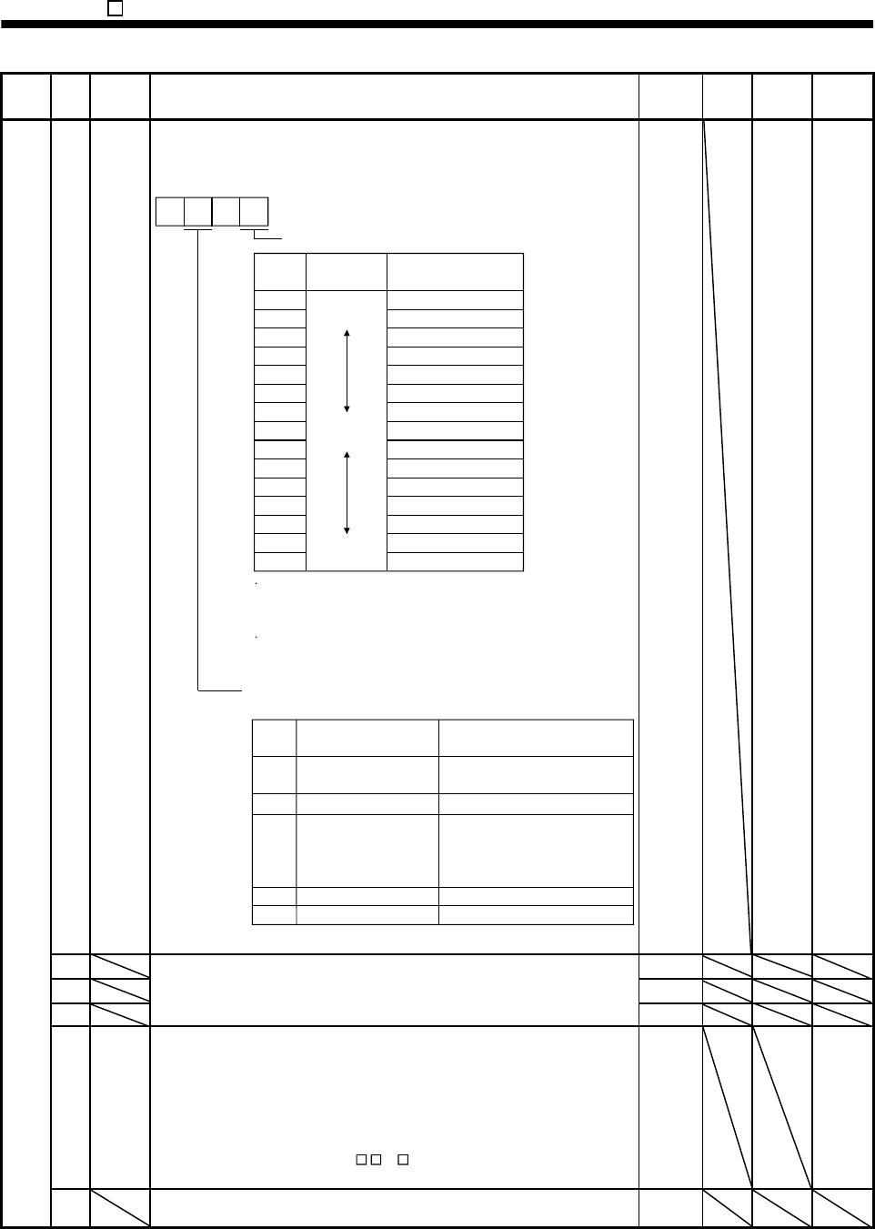
2 ATU Auto tuning
Used to selection the response level, etc. for execution of auto tuning.
Refer to Chapter 7.
Auto tuning response level setting
If the machine hunts or generates
large gear sound, decrease the
set value.
To improve performance, e.g.
shorten the settling time, increase
the set value.
Set
value
Response
level
1
Low
response
Middle
response
High
response
Gain adjustment mode selection
(For more information, refer to Section 7.1.1.)
Machine resonance
frequency guideline
15Hz
2
20Hz
3
25Hz
4
30Hz
5
35Hz
6
45Hz
7
55Hz
8
70Hz
9
85Hz
A
105Hz
B
130Hz
C
160Hz
D
200Hz
E
240Hz
F300Hz
Set
value
Gain adjustment mode
0
Description
1
3 Simple manual adjustment.
4 Manual adjustment of all gains.
Interpolation mode
Fixes position control gain 1
(parameter No. 6).
Auto tuning mode 1
Fixes the load inertia moment
ratio set in parameter No. 34.
Response level setting can be
changed.
Manual mode 1
Manual mode 2
2
Auto tuning mode 2
Ordinary auto tuning.
0 0
0105
Refer to
Name
and
function
column.
S
3 1
4 1
5
For manufacturer setting
Don’t change this value by anymeans.
100
6 PG1 Position loop gain 1
Used to set the gain of position loop.
Increase the gain to improve trackability in response to the position
command.
When auto turning mode 1,2 is selected, the result of auto turning is
automatically used.
To use this parameter, set "
1 " to parameter No. 20 to validate
servo lock at stop.
35 S
Basic parameters
7 For manufacturer setting
Don’t change this value by anymeans.
3


