


1 - 9
1. FUNCTIONS AND CONFIGURATION
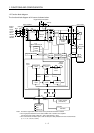
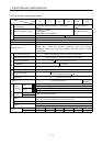
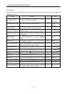
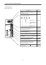
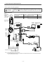
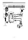
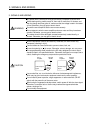
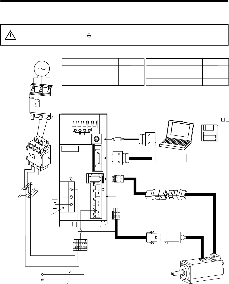
1.8 Servo system with auxiliary equipment
WARNING
To prevent an electric shock, always connect the protective earth (PE) terminal
(terminal marked
) of the servo amplifier to the protective earth (PE) of the control
box.
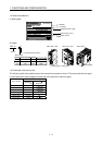
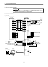
(1) MR-E-100A or less
MODE
CN3
SET
CN1
CN2
CNP2
CNP1
L3L2L1D C P W V U
CHARGE
MITSUBISHI
MR-E-
P
C
L
3
L
2
L
1
(Note 2)
3-phase 200V
to 230VAC power
supply or
1-phase 230VAC
power supply
No-fuse breaker
(NFB) or fuse
Magnetic
contactor
(MC)
To CN2
To CN1
To CN3
Protective earth
(PE) terminal
Servo motor
Personal
computer
Servo amplifier
Regenerative option
Options and auxiliary equipment
No-fuse breaker
Magnetic contactor
Servo configuration software
Regenerative option
Refer to
Section 13.2.2
Section 13.2.2
Section 13.1.4
Section 13.1.1
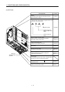
(Note 1)
Encoder cable
Options and auxiliary equipment
Refer to
Cables
Section 13.2.1
Command device
(Note 1)
Power supply lead
Power
factor
improving
reactor
(FR-BAL)
Power factor improving reactor
Section 13.2.3
Servo configuration
software
MRZJW3-SETUP1
Note: 1. The HC-SFE series have cannon connectors.
2. A 1-phase 230VAC power supply may be used with the servo amplifier of MR-E-70A or less. Connect the power supply to
L
1
and L
2
terminals and leave L
3
open.