


15 - 4
15. MR-E-
AG SERVO AMPLIFIER COMPATIBLE WITH ANALOG INPUT
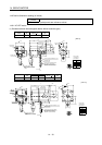
15.1.4 Model code definition
AG
70
750
40 400
10
100
20
100
200
1000
200 2000
MR-E-200AGMR-E-40AG or less MR-E-70AG, 100AG
Rating plate Rating plate
Rating plate
Series
Rated output
Analog input
Symbol
Rated output [W]
Symbol
Rated output [W]
- MR - E
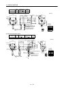
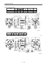
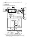
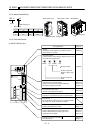
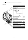
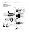
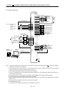
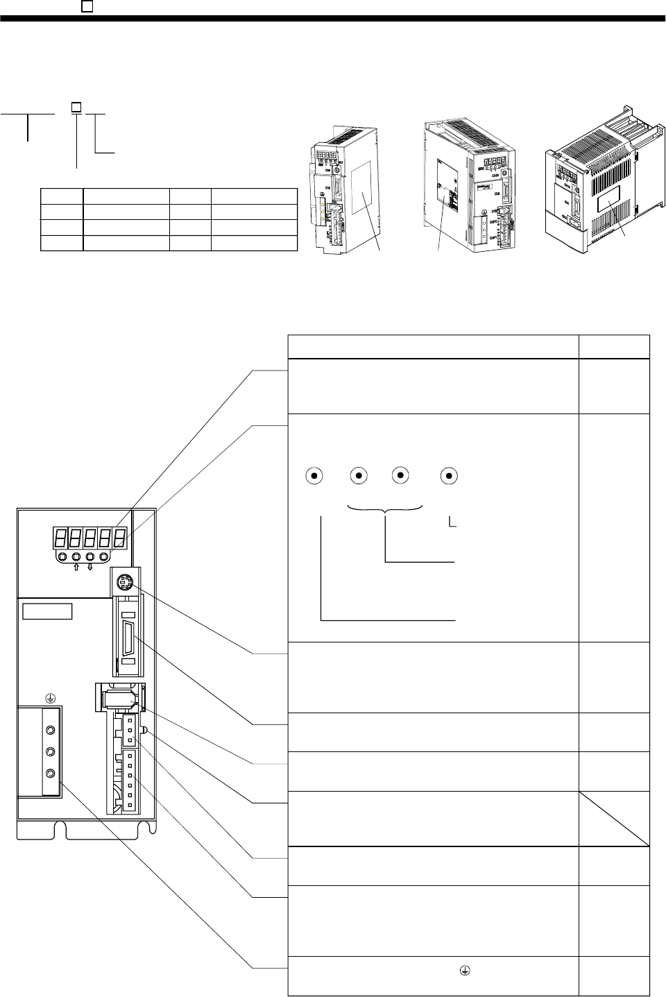
15.1.5 Parts identification
(1) MR-E-100AG or less
MODE
CN3
SET
CN1
CN2
CNP2
CNP1
L3L2L1 D C P W V U
CHARGE
MITSUBISHI
MR-
Chapter6
Display
The 5-digit, seven-segment LED shows the servo
status and alarm number.
Used to set data.
Used to change the
display or data in each
mode.
Used to change the
mode.
MODE
UP
DOWN
SET
Operation section
Used to perform status display, diagnostic, alarm and
parameter setting operations.
Chapter6
Communication connector (CN3)
Used to connect a command device (RS-232C)
and output analog monitor data.
I/O signal connector (CN1)
Used to connect digital I/O signals.
Section3.3
Encoder connector (CN2)
Connector for connection of the servo motor encoder.
Section3.3
Section13.1.2
Charge lamp
Lit to indicate that the main circuit is charged. While
this lamp is lit, do not reconnect the cables.
Protective earth (PE) terminal ( )
Ground terminal.
Section3.10
Section11.1
Section3.3
Section13.1.2
Chapter14
Section3.7
Section11.1
Section3.7
Section11.1
Section13.1.1
Refer to
Name/Application
Motor power supply connector (CNP2)
Used to connect the servo motor.
Power supply/regenerative connector (CNP1)
Used to connect the input power supply and
regenerative brake option.