


13 - 16
13. OPTIONS AND AUXILIARY EQUIPMENT
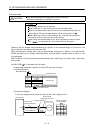
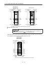
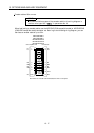
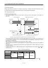
2) Connection diagram
For the pin assignment on the servo amplifier side, refer to Section 3.3.1.
CN2
A
B
C
D
E
F
G
H
J
K
L
M
A
B
C MR
D
MRR
E
F
G
H
J
K
L
M
N SHD
P
R LG
S
P5
T
Servo amplifier
50m(164.0ft) max.
Encoder connector
Servo motor
Encoder
Encoder connector
Pin Signal
Encoder cable
(Optional or fabricated)
Pin Signal
R
S
T
P
N
MD
MDR
CONT
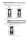
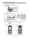
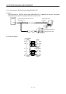
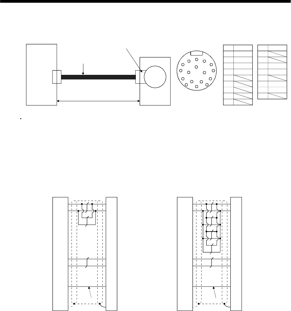
Encoder cable of less than 30m
When fabricating an encoder cable, use the MR-ECNS (IP20-compatible model) or MR-ENECNS
(IP65/IP67-compatible model) connector set. Referring to the following wiring diagram, you can
fabricate an encoder cable of up to less than 30m.
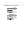
MRRMRR
P5
LG
1
2
MR 3
4
F
S
9
SD
C
D
R
N
MR-ESCBL20M-H
MR-ENECBL20M-H
P5G
MR
MRR
SHD
P5E
P5
LG
1
2
MR 3
4
F
S
9
SD
C
D
R
N
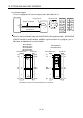
MR-ESCBL2M-H
MR-ESCBL5M-H
MR-ESCBL10M-H
MR-ENECBL2M-H
MR-ENECBL5M-H
MR-ENECBL10M-H
P5G
MR
MRR
SHD
P5E
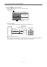
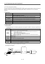
Servo amplifier side Encoder side
Plate Plate
Servo amplifier side Encoder side
(Note) (Note)
Note. When an encoder cable is fabricated, this wire is not required.