14 - 34
14. SERVO MOTOR
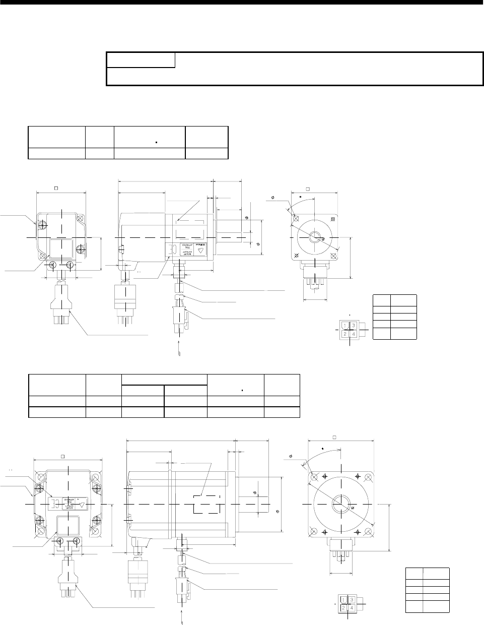
14.9 Outline dimension drawing (in inches)
POINT
The values in yards/pounds are reference values.
14.9.1 HC-KFE series
(1) Standard (without electromagnetic brake, without reduction gear)
Model
Output
[W]
Inertia Moment
WK
2
[oz in
2
]
Weight
[lb]
HC-KFE13 100 0.459 1.17
Power supply
connector pin
connection list
1
2
3
4
Pin No. Application
Phase U
Phase V
Phase W
Earth
BC24190*
0.737
5557-04R-210 (Receptacle)
5556PBTL (Female terminal)
With connector 1-172169-9
(AMP)
Arrow A
1.406
Bottom
Top
Protective tube
Motor plate
(Opposite side)
1.181
1.81
1.575
0.315
Power supply connector (Molex)
Encoder cable 11.8 in
Motor plate
Caution plate
Bottom
Top
Top
0.984
0.098
0.197
1.59
0.268
0.39
0.992
1.65
1.13
2- 0.177
Power supply lead 4-AWG19 11.8 in
TUV plate
Arrow A
Bottom
Top
Bottom
3.70
0.846
1.75
45
[Unit: in]
Top
Bottom
Variable Dimensions [in]
Model
Output
[W]
LKL
Inertia Moment
WK
2
[oz in
2
]
Weight
[lb]
HC-KFE23 200 3.92 1.93 2.296 2.183
HC-KFE43 400 4.90 2.84 3.663 3.197
[Unit: in]
0.737
5557-04R-210 (Receptacle)
5556PBTL (Female terminal)
With connector 1-172169-9
(AMP)
Arrow A
1.685
Bottom
Top
Protective tube
Motor plate
(Opposite side)
1.969
2.758
2.362
0.551
Power supply connector (Molex)
Encoder cable 11.8 in
Motor plate
Caution plate
Bottom
Top
KL
1.181
0.118
0.276
L
1.614
0.417
0.390
0.992
3.23
1.512
4- 0.228
Power supply lead 4-AWG19 11.8 in
TUV plate
Arrow A
Top
Bottom
0.106
45
Power supply
connector pin
connection list
1
2
3
4
Pin No. Application
Phase U
Phase V
Phase W
Earth
BC24191*
Top
Bottom


