


2
1
.1 Japanese Version
1
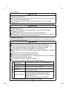
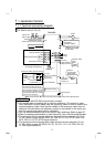
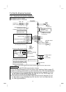
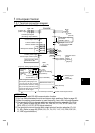
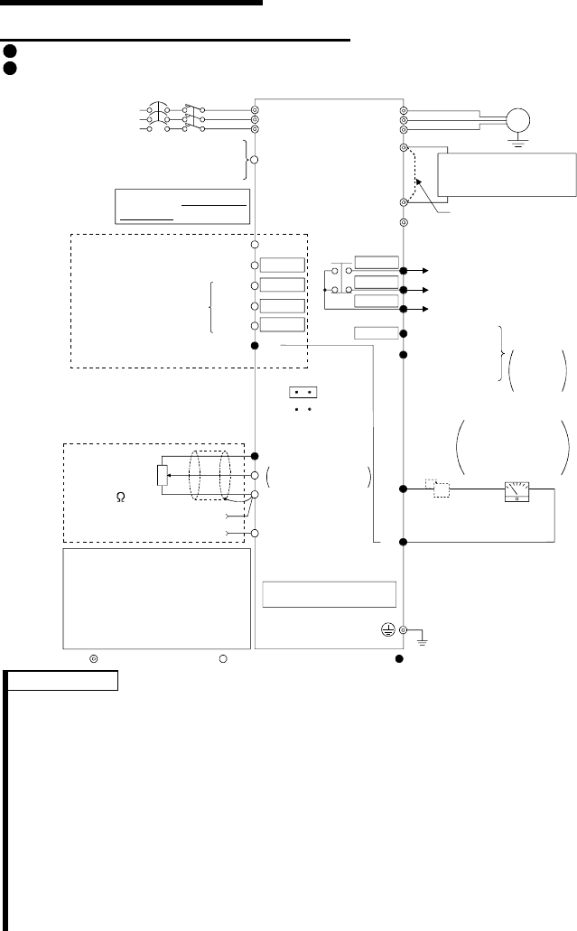
.1.1 Terminal connection diagram
FR-S520-0.1K to 3.7K (-R) (-C)
FR-S540-0.4K to 3.7K (-R)
Power factor improving
DC reactor
(FR-BEL: Option)
PC
External transistor common
24VDC power supply
Contact input common (source)
STF
STR
RH
RM
RL
SD
Forward rotation start
Reverse rotation start
Middle
High
Low
Frequency setting signals (Analog)
10 (+5V)
2
2
3
1
4 to 20mADC (+)
4 (4 to 20mADC)
Frequency
setting
potentiometer
1/2W1k
(*4)
SE
Running
FM
SD
Control input signals
(No voltage input allowed)
Jumper:
Remove this
jumper when FR-BEL
is connected.
Motor
IM
Ground
Alarm
output
U
V
W
P1
P
N
(+) (-)
Earth (Ground)
Selected
Multi-speed selection
Operation status
output
Contact input common
5 (Common)
Open collector
output common
Current input (-)
3-phase AC
power supply
NFB
R
S
T
MC
Open
collector
outputs
Calibration
resistor (*2)
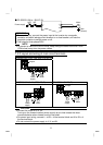
SINK
SOURCE
RS-485 Connector (*1)
Inverter
Main circuit terminal Control circuit input terminal Control circuit output terminal
DC 0 to 5V
DC 0 to 10V
Indicator
1mA full-scale
Analog meter
(Digital indicator)
1mA
(*3)
When using the current input as
the frequency setting signal, set
"4" in any of Pr. 60 to Pr. 63 (input
terminal function selection), assign
AU (current input selection) to any
of terminals RH, RM, RL and STR,
and turn on the AU signal.
(Note)
Be careful not to short
terminals PC-SD.
*5
*5
*5
*5
RUN
*6
C
*6
B
*6
A
*6
REMARKS
*1 Only the type with RS-485 communication function.
*2 Not needed when the setting dial is used for calibration. This resistor is used
when calibration must be made near the frequency meter for such a reason as a
remote frequency meter. Note that the needle of the frequency meter may not
deflect to full-scale when the calibration resistor is connected. In this case, use
both the resistor and setting dial for calibration.
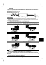
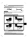
*3 You can switch between the sink and source logic positions. Refer to page 25.
*4 When the setting potentiometer is used frequently, use a 2W1kΩ potentiometer.
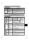
*5 The terminal functions change with input terminal function selection (Pr. 60 to
Pr. 63). (Refer to page 38, 88) (RES, RL, RM, RH, RT, AU, STOP, MRS, OH,
REX, JOG, X14, X16, (STR) signal selection)
*6 The terminal functions change with output terminal function selection (Pr. 64,
Pr. 65). (Refer to page 90) (RUN, SU, OL, FU, RY, Y12, Y13, FDN, FUP, RL,
LF, ABC signal selection)