


5
1
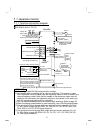
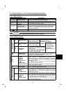
NOTE
To prevent a malfunction due to noise, keep the signal cables more than 10cm
(3.94inches) away from the power cables.
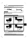
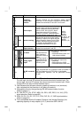
FR-S510W-0.1K to 0.75K-NA
Power supply
NFB
R
S
Motor
IM
Earth
(
Ground
)
U
V
W
MC
REMARKS
• To ensure safety, connect the power input to the inverter via a magnetic contactor
and earth leakage circuit breaker or no-fuse breaker, and use the magnetic
contactor to switch power on-off.
• The output is three-phase 200V.
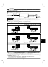
1
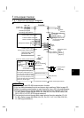
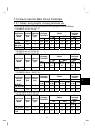
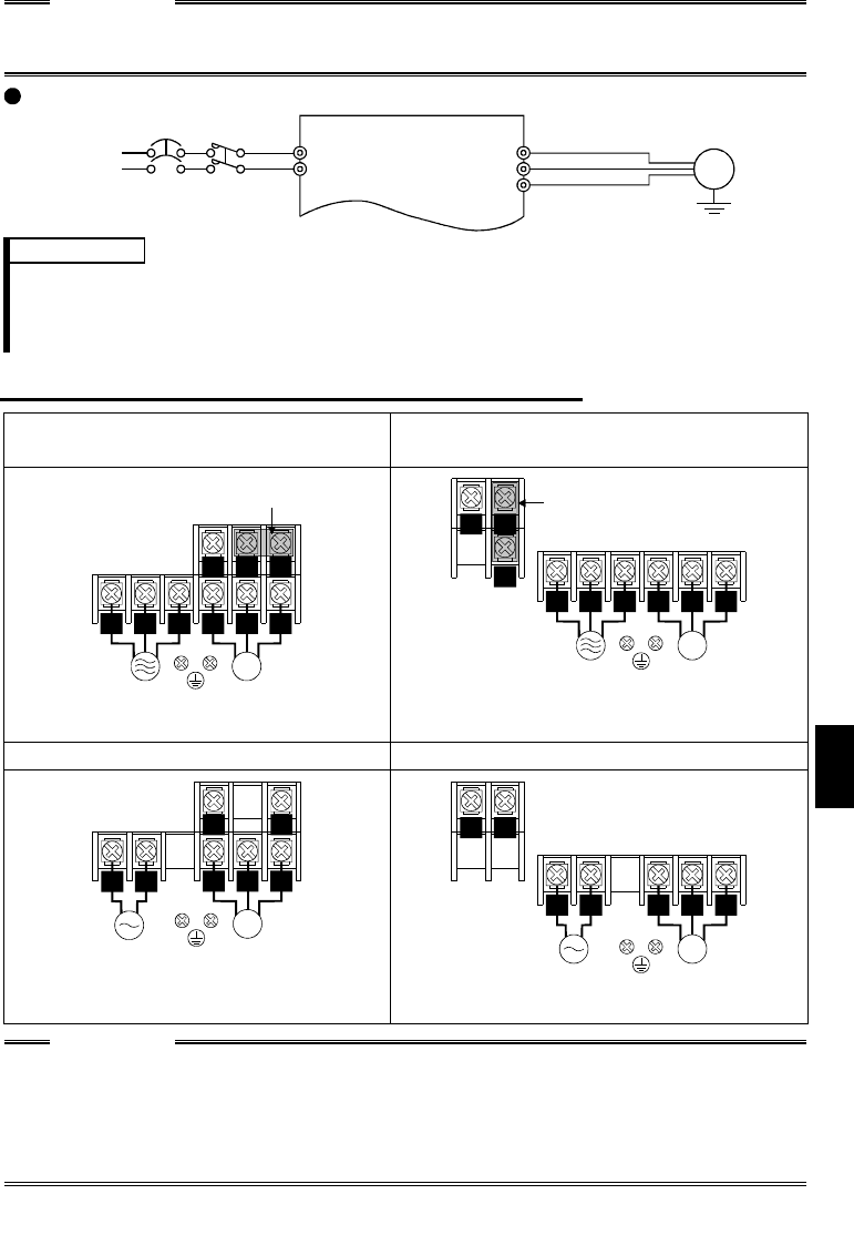
.2.2 Layout and wiring of main circuit terminals
FR-S520-0.1K, 0.2K, 0.4K, 0.75K-NA
FR-S520-1.5K, 2.2K, 3.7K-NA
FR-S540-0.4K, 0.75K, 1.5K, 2.2K, 3.7K-NA (R)
P1
U V W
IM
RST
NP
Jumper
Power
supply
Motor
P1
Jumper
R S T U V W
IM
NP
Power
supply
Motor
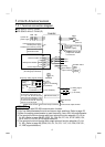
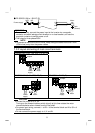
FR-S510W-0.1K, 0.2K, 0.4K-NA FR-S510W-0.75K-NA
U V W
IM
NP
RS
Power
supply
Motor
U V W
IM
NP
RS
Power
suppl
y
Motor
CAUTION
• The power supply cables must be connected to R, S, T. If they are connected to
U, V, W, the inverter will be damaged. (Phase sequence need not be matched.)
• Connect the motor to U, V, W.
Turning on the forward rotation switch (signal) at this time rotates the motor
counterclockwise when viewed from the load shaft.