


44
1
.10 Design Information
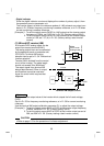
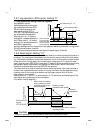
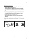
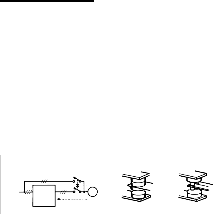
1) Provide electrical and mechanical interlocks for MC1 and MC2 which are used for
commercial power supply-inverter switch-over.
When there is a commercial power supply-inverter switch-over circuit as shown
below, the inverter will be damaged by leakage current from the power supply due
to arcs generated at the time of switch-over or chattering caused by a sequence
error.
2) If the machine must not be restarted when power is restored after a power failure,
provide a magnetic contactor in the inverter's primary circuit and also make up a
sequence which will not switch on the start signal.
If the start signal (start switch) remains on after a power failure, the inverter will
automatically restart as soon as the power is restored.
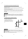
3) Since the input signals to the control circuit are on a low level, use two or more
parallel micro signal contacts or a twin contact for contact inputs to prevent a
contact fault.
4) Do not apply a large voltage to the contact input terminals (e.g. STF) of the control
circuit.
5) Always apply a voltage to the alarm output terminals (A, B, C) via a relay coil, lamp
etc.
6) Make sure that the specifications and rating match the system requirements.
1) Commercial power supply-inverter
switch-over
U
V
W
R<L
1
>
S<N>
T
IM
MC2
MC1
Power
supply
Inverter
Leakage current
Interlock
3) Low-level signal contacts
Low-level signal contacts Twin contact