


37
1
1
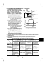
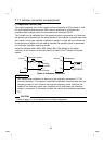
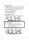
.7.5 Control circuit common terminals (SD, 5, SE)
Terminals SD, 5, and SE are all common terminals (0V) for I/O signals and are
isolated from each other.
Terminal SD is a common terminal for the contact input terminals (STF, STR, RH, RM,
RL) and frequency output signal (FM).
Terminal 5 is a common terminal for the frequency setting analog input signals and
indicator terminal "AM". It should be protected from external noise using a shielded or
twisted cable.
Terminal SE is a common terminal for the open collector output terminal (RUN).
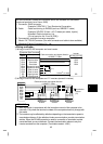
REMARKS
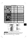
Terminal FM is provided for the FR-S520-0.1K to 3.7K (-R) (-C), FR-S520S-0.1K to
1.5K (-R) and FR-S510W-0.1K to 0.75 (-R), and terminal AM is provided for the
FR-S520-0.1K to 3.7K-NA, FR-S520S-0.2K to 1.5K-EC (R) and FR-S510W-0.1K to
0.75K-NA.
1
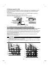
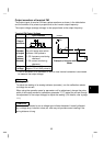
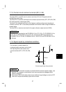
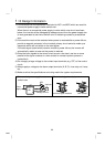
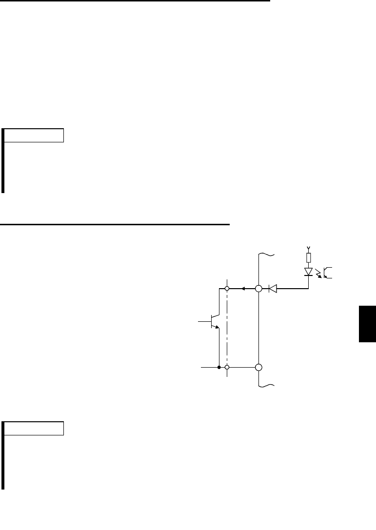
.7.6 Signal inputs by contactless switches
If a transistor is used instead of a
contacted switch as shown on the right,
the input signals of the inverter can
control terminals STF, STR, RH, RM,
RL.
+24V
STF, etc.
SD
Inverter
External signal input using transisto
r
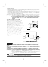
REMARKS
1. When using an external transistor connected with the external power supply, use
terminal PC to prevent a malfunction from occurring due to a leakage current.
(Refer to page 25.)
2. Note that an SSR (solid-state relay) has a relatively large leakage current at OFF
time and it may be accidentally input to the inverter.