


119
2
REMARKS
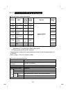
• For computer link operation, set 65520 (HFFF0) as the value "888" and 65535
(HFFFF) as the value "- - -".
• Refer to page 41 for handling the RS-485 connector.
• Refer to the "parameter data code list" (page 177) for the data codes of the
parameters.
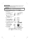
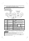
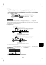
<Setting>
To make communication between the personal computer and inverter, the
communication specifications must be set to the inverter initially. If initial setting is not
made or there is a setting fault, data transfer cannot be made.
Note: After making the initial setting of the parameters, always reset the inverter. After
you have changed the communication-related parameters, communication
cannot be made unit the inverter is reset.
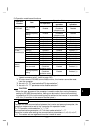
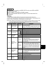
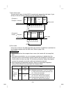
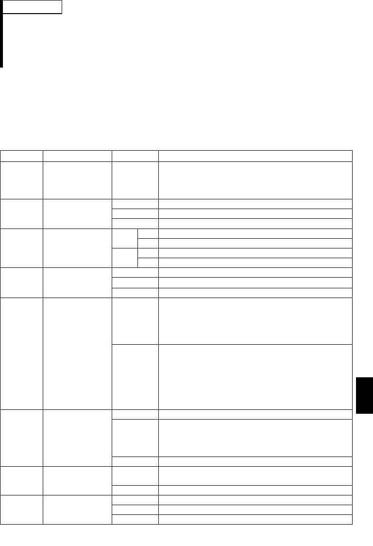
Parameter Description Setting Description
n1
Communication
station number
0 to 31
Station number specified for communication from
the RS-485 connector.
Set the inverter station numbers when two or more
inverters are connected to one personal computer.
48 4800 bps
96 9600 bps
n2
Communication
speed
192 19200 bps
0 Stop bit length 1 bit
8 bits
1 Stop bit length 2 bits
10 Stop bit length 1 bit
n3 Stop bit length
7 bits
11 Stop bit length 2 bits
0 Absent
1 Odd parity presentn4
Parity check
presence/
absence
2 Even parity present
0 to 10
Set the permissible number of retries at occurrence
of a data receive error.
If the number of consecutive errors exceeds the
permissible value, the inverter will come to an
alarm stop (OPT).
n5
Number of
communication
retries
- - -
(65535)
If a communication error occurs, the inverter will
not come to an alarm stop. At this time, the inverter
can be coasted to a stop by MRS or RES input.
During a communication error (H0 to H5), the minor
fault signal (LF) is switched on. Allocate the used
terminal with any of Pr. 64, Pr. 65 (multi-function
outputs).
0 No communication
0.1 to 999
Set the communication check time [s] interval.
If a no-communication state persists for longer than
the permissible time, the inverter will come to an
alarm stop (OPT).
n6
Communication
check time
interval
- - - Communication check suspension
0 to 150
Set the waiting time between data transmission to
the inverter and response.
n7 Wait time setting
- - - Set with communication data.
0 Without CR
•
LF
1 With CR, without LFn11
CR
•
LF
selection
2 With CR
•
LF