


9
1
1
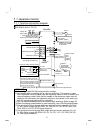
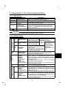
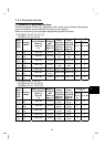
.4 Description of I/O Terminal Specifications
1
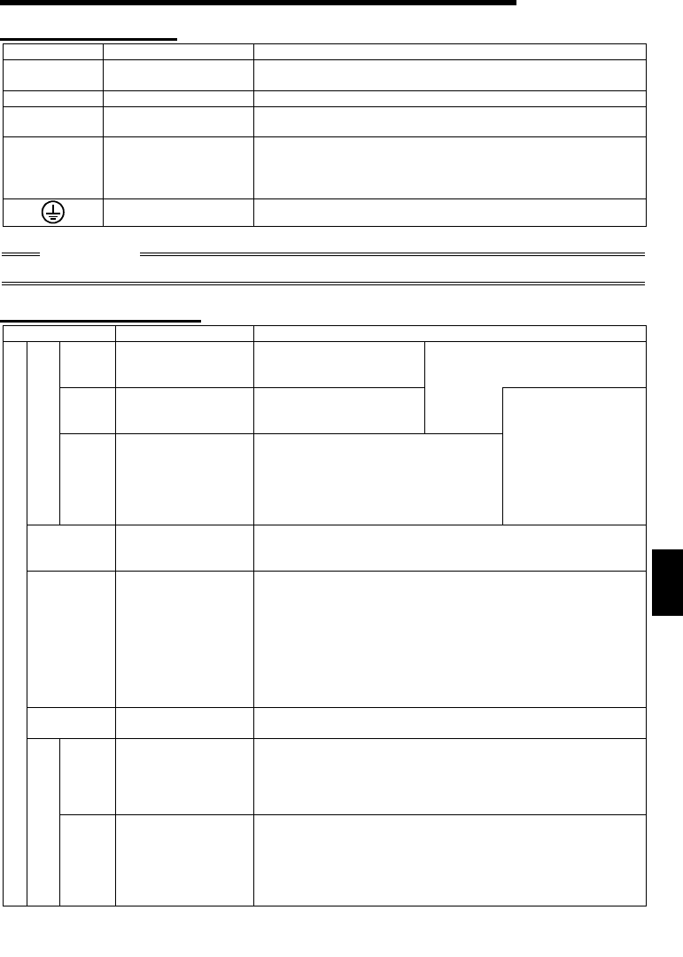
.4.1 Main circuit
Symbol Terminal Name Description
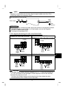
R, S, T *
<L
1
, L
2
, L
3
>
AC power input
Connect to the commercial power supply.
U, V, W Inverter output
Connect a three-phase squirrel-cage motor.
N<->
DC voltage
common
DC volta
g
e common terminal. Not isolated from the
power supply and inverter output.
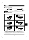
P<+>, P1
Power factor
improving DC
reactor connection
Disconnect the jumper from terminals P<+>-P1 and
connect the optional power factor improving DC reactor
(FR-BEL). (The single-phase 100V power input model
cannot be connected.)
Earth (Ground)
For grounding the inverter chassis. Must be earthed.
* R, S <L
1
, N> terminals for single-phase power input.
CAUTION
< >Terminal names in parentheses are those of the EC version.
1
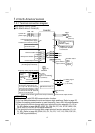
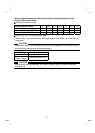
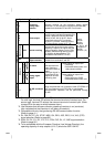
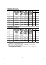
.4.2 Control circuit
Symbol Terminal Name Description
STF
Forward rotation
start
Turn on the STF si
g
nal
to start forward rotation
and turn it off to stop.
When the STF and STR
signals are turned on
simultaneously, the stop
STR
Reverse rotation
start
Turn on the STR signal
to start reverse rotation
and turn it off to stop.
command
is given.
Contact input
RH
RM
RL
Multi-speed
selection
Turn on the RH, RM and RL signals
in appropriate combinations to select
multiple speeds.
The priorities of the speed commands
are in order of jog, multi-speed setting
(RH, RM, RL, REX) and AU.
Input terminal
function selection
(Pr. 60 to Pr. 63)
changes the
terminal functions.
(*4)
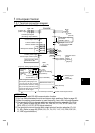
SD
(*1)
Contact input
common (sink)
Common terminal for contact inputs (terminals STF, STR,
RH, RM, RL) and indicator connection (terminal FM).
Isolated from terminals 5 and SE.
PC
(*1)
External
transistor
common
24VDC power
supply
Contact input
common
(
source
)
When connectin
g
the transistor output
(
open collector
output
)
, such as a pro
g
rammable controller
(
PLC
)
,
connect the positive external power suppl
y
for transistor
output to this terminal to prevent a malfunction caused by
undesirable current.
This terminal can be used as a 24V 0.1A DC power
output across terminals PC-SD.
When source lo
g
ic is selected, this terminal serves as a
contact input signal common.
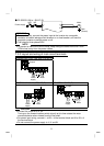
10
Frequency setting
power supply
5VDC. Permissible load current 10mA.
2
Frequency
setting
(Voltage signal)
B
y
enterin
g
0 to 5VDC
(
0 to 10VDC
)
, the maximum
output frequenc
y
is reached at 5V
(
10V
)
and I/O are
proportional. Use Pr. 73 "0-5V/0-10V selection" to switch
between 5V and 10V.
Input resistance 10k
Ω
. Maximum permissible voltage 20V.
Input signals
Frequency setting
4
Frequency
setting
(Current signal)
Enter 4-20mADC. This si
g
nal is factor
y
-ad
j
usted to reach
0Hz at 4mA and 60Hz at 20mA. Maximum permissible
input current 30mA. Input resistance approximately 250
Ω
.
For current input, turn on the signal AU.
Set the AU si
g
nal in an
y
of Pr. 60 to Pr. 63
(
input
terminal function selection).