


I
CONTENTS
1. WIRING 1
1.1 Japanese Version.....................................................................................2
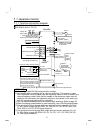
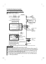
1.1.1 Terminal connection diagram .................................................................... 2
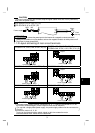
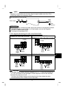
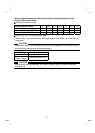
1.1.2 Layout and wiring of main circuit terminals............................................... 3
1.2 North America Version.............................................................................4
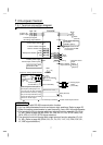
1.2.1 Terminal connection diagram .................................................................... 4
1.2.2 Layout and wiring of main circuit terminals............................................... 5
1.3 European Version.....................................................................................7
1.3.1 Terminal connection diagram .................................................................... 7
1.3.2 Layout and wiring of main circuit terminals............................................... 8
1.4 Description of I/O Terminal Specifications ...............................................9
1.4.1 Main circuit .................................................................................................. 9
1.4.2 Control circuit .............................................................................................. 9
1.5 How to Use the Main Circuit Terminals..................................................11
1.5.1 Cables, wiring lengths, crimping terminals, etc. ..................................... 11
1.5.2 Wiring instructions .................................................................................... 12
1.5.3 Peripheral devices ....................................................................................13
1.5.4 Leakage current and installation of earth leakage circuit breaker...... 15
1.5.5 Power-off and magnetic contactor (MC)................................................. 17
1.5.6 Regarding the installation of the power factor improving reactor ....... 18
1.5.7 Regarding noise and the installation of a noise filter.............................. 18
1.5.8 Grounding precautions............................................................................. 19
1.5.9 Regarding power harmonics..................................................................... 20
1.5.10 Japanese power harmonic suppression guideline............................... 20
1.6 How to Use the Control Circuit Terminals..............................................24
1.6.1 Terminal block layout................................................................................ 24
1.6.2 Wiring instructions .................................................................................... 24
1.6.3 Changing the control logic........................................................................ 25
1.7 Input Terminals.......................................................................................28
1.7.1 Run (start) and stop (STF, STR, STOP)................................................. 28
1.7.2 Connection of frequency setting potentiometer and output frequency
meter (10, 2, 5, 4, AU).............................................................................. 31
1.7.3 External frequency selection (REX, RH, RM, RL).................................. 32
1.7.4 Indicator connection and adjustment ...................................................... 34
1.7.5 Control circuit common terminals (SD, 5, SE)........................................ 37
1.7.6 Signal inputs by contactless switches..................................................... 37
1.8 How to Use the Input Signals
(Assigned Terminals RL, RM, RH, STR)................................................38
1.8.1
Multi-speed setting (RL, RM, RH, REX signals): Setting "0, 1, 2, 8"
Remote setting (RL, RM, RH signals): Setting "0, 1, 2"......................... 38
1.8.2 Second function selection (RT signal): Setting "3"................................. 38
Contents