173
(8) Cable thickness and wiring distance
If the inverter-to-motor wiring distance is long, the motor torque will decrease
due to a voltage drop in the main circuit cables especially at low frequency
output. Use thick cables for wiring to make a voltage drop less than 2%. (A
selection example for the wiring distance of 20m (65.62feet) is given on page
11.)
For remote operation using analog signals, the control cable between operator
box or operator signal and inverter should be less than 30m (98.43feet) and
wire the cable away from the power circuit to avoid induction from other
equipment.
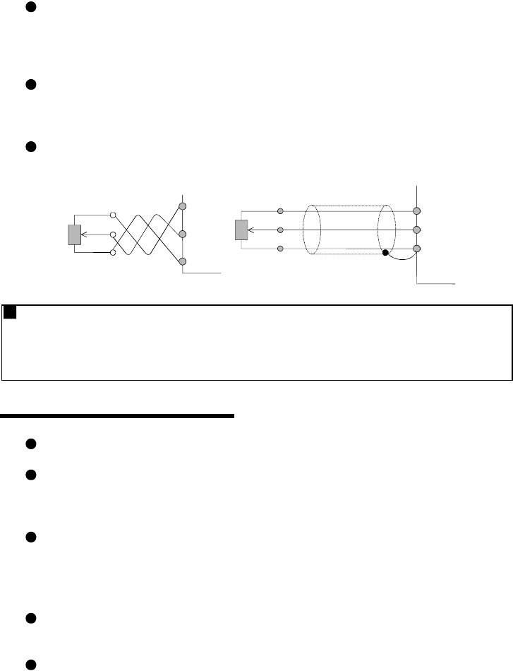
When using the external potentiometer to set the frequency, use a shielded or
twisted cable, and do not earth the shield, but connect it to terminal 5 as shown
below.
Twisted
cable
Frequency
setting
p
otentiometer
(3)
(1)
(2)
10
2
5
Frequency
setting
potentiometer
Shielded cable
(3)
(2)
(1)
10
2
5
Grounding
When the inverter is run in the low acoustic noise mode, high-speed switching will
generate more leakage currents than in the non-low acoustic noise mode. Always
ground the inverter and motor. In addition, always use the ground terminal of the
inverter to ground the inverter.
5
.3 Operating Instructions
(1) Operation
When a magnetic contactor (MC) is provided on the primary side, do not use
this MC to make frequent starts/stops. Doing so can cause the inverter to fail.
When an alarm occurs in the inverter, the protective function is activated to stop
the output. However, at this time, the motor cannot be brought to a sudden
stop. Hence, provide a mechanical stopping/holding mechanism for the
machine/equipment which requires an emergency stop.
Since the capacitor needs time to discharge, do not start inspection
immediately after powering off the inverter. More than 10 minutes after power-
off, make sure that there are no residual voltages with a multimeter etc. before
stating inspection.
(2) Wiring
Application of power to the output terminals (U, V, W) of the inverter will
damage the inverter circuit. Hence, before power-on, fully check the wiring and
sequence for incorrect wiring and so on.
Terminals P<+> and P1 are designed to connect a dedicated option. Do not
connect any equipment other than the dedicated option. In addition, do not
short the frequency setting power supply terminal 10 and common terminal 5,
and terminals PC-SD.


