


158
3
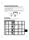
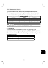
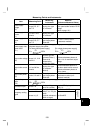
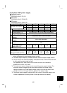
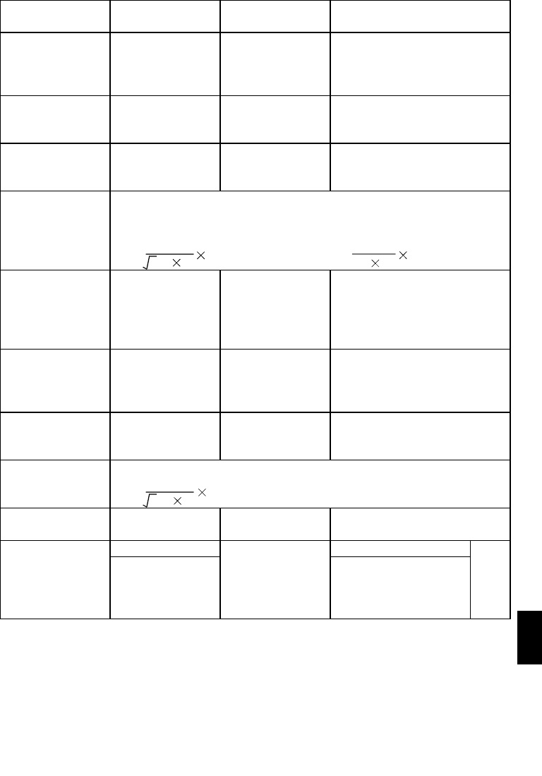
Measuring Points and Instruments
Item Measuring Point
Measuring
Instrument
Remarks
(Reference Measured Value)
Power supply
voltage
(V1)
Across R-S, S-T
and T-R
Moving-iron type
AC voltmeter
Is the commercial power supply
within permissible variation of AC
voltage
(Refer to page 161)
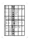
Power supply side
current
(I1)
R, S and T line
currents
Moving-iron type
AC ammeter
Power supply side
power
(P1)
At R, S and T, and
across R-S, S-T
and T-R
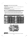
Electrodynamic
type single-phase
wattmeter
P1 = W11 + W12 + W13
(3-wattmeter method)
Power supply side
power factor
(Pf1)
Calculate after measuring power supply voltage, power supply side current
and power supply side power.
[For three-phase power supply] [For single-phase power supply]
Pf1=
P1
3V1 I1
100%
Pf1=
P1
V1 I1
100%
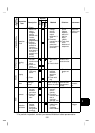
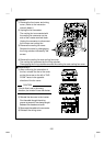
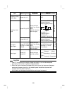
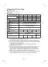
Output side voltage
(V2)
Across U-V, V-W
and W-U
Rectifier type AC
voltmeter (Note 1)
(Cannot be
measured by
moving-iron type)
Difference between phases is
within
±
1% of maximum output
voltage.
Output side current
(I2)
U, V and W line
currents
Moving-iron type
AC ammeter
(Note 2)
Current should be equal to or
less than rated inverter current.
Difference between phases is
10% or lower.
Output side power
(P2)
At U, V and W, and
across U-V and V-
W
Electrodynamic
type single-phase
wattmeter
P2 = W21 + W22
2-wattmeter method (or 3-
wattmeter method)
Output side power
factor
(Pf2)
Calculate in similar manner to power supply side power factor.
Pf2=
P2
3V2 I2
100%
Converter output Across P-N
Moving-coil type
(such as a meter)
Inverter LED display is lit.
1.35 × V1
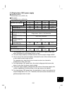
Across 2 (+)-5 0 to 5V/0 to 10VDC
Frequency setting
signal
Across 4 (+)-5
Moving-coil type
(Meter, etc. may be
used)
(Internal resistance:
50k
Ω
or larger)
4 to 20mADC
"5" is
common.