


129
2
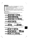
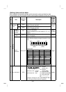
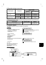
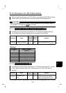
(5) Operation at alarm occurrence
Operation Mode
Fault Location Description
Communication
Operation
(
RS-485 connector
)
External O
p
eration
Inverter operation Stop Stop
Inverter fault
Communication
RS-485
connector
Continued Continued
Inverter operation Stop/continued (*3) Continued
Communication error
(Communication from
RS-485 connector)
Communication
RS-485
connector
Stop Stop
*3: Can be selected using the corresponding parameter (factory-set to stop).
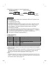
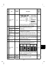
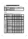
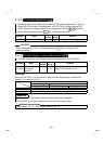
(6) Communication error
Fault Location
Error Message
(Operation panel)
Remarks
Communication error
(Communication from RS-485 connector)
OPT Error code is OPT
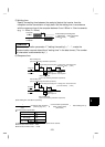
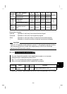
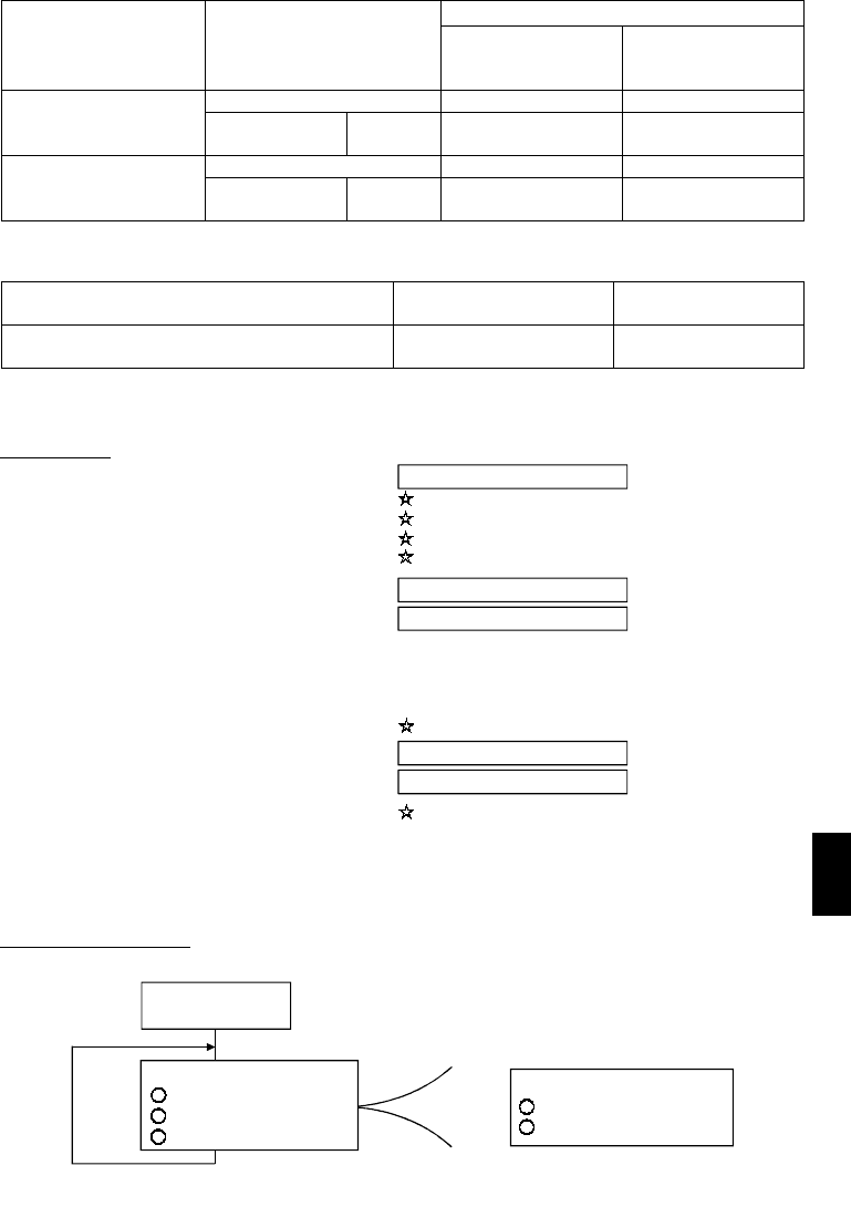
(7) Program example
To change the operation mode to computer link operation
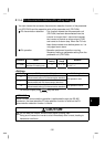
Program
1000 *REC
1010 IF LOC(1)=0 THEN RETURN
1020 PRINT"RECEIVE DATA"
1040 RETURN
140 GOTO 50
Interrupt data receive
1030 PRINT INPUT$(LOC(1),#1)
130 PRINT#1,D$
Data send
Initial setting of I/O fileLine number
Interrupt occurrence during data receive
30 ON COM(1)GOSUB*REC
20 COMST1,1,1:COMST1,2,1
10 OPEN"COM1:9600,E,8,2,HD"AS #1
Opening the communication file
40 COM(1)ON
50 D$="01FB10000"
Send data setting
Sum code calculation
80 A$=MID$(D$,I,1)
90 A=ASC(A$)
100 S=S+A
110 NEXT I
70 FOR I=1 TO LEN(D$)
60 S=0
Addition of control and sum codes
120 D$=CHR$(&H5)+D$+RIGHT$(HEX$(S),2)
ON/OFF setting of circuit control signals (RS, ER)
Interrupt enable
Interrupt definition for data receive
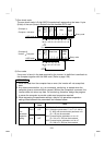
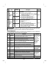
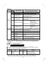
General flowchart
Data import
50
140
Data send
10
40
to
to
Line number
I/O file initial
setting
to
1000
1040
Interrupt
Receive data processing
Screen display
Sum code calculation
Send data processing
Data setting