


20
1
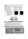
.5.9 Regarding power harmonics
The inverter may generate power harmonics from its converter circuit to affect the
power generator, power capacitor etc. Power harmonics are different from noise and
leakage currents in source, frequency band and transmission path. Take the following
counter measure suppression techniques.
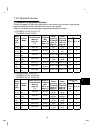
The following table indicates differences between harmonics and noise:
Item Harmonics Noise
Frequency
Normall
y
40th to 50th de
g
rees or
less (up to 3kHz or less)
Hi
g
h frequenc
y
(
several 10kHz
to MHz order)
Environment
To-electric channel, power
impedance
To-space, distance, wiring path
Quantitative
understanding
Theoretical calculation possible
Random occurrence, quantitative
grasping difficult
Generated amount
Nearly proportional to load
capacity
Chan
g
e with current variation
ratio
(
lar
g
er as switchin
g
speed
increases)
Affected equipment
immunity
Specified in standard per
equipment
Different dependin
g
on maker's
equipment specifications
Suppression example
Provide reactor. Increase distance.
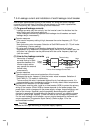
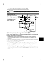
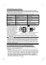
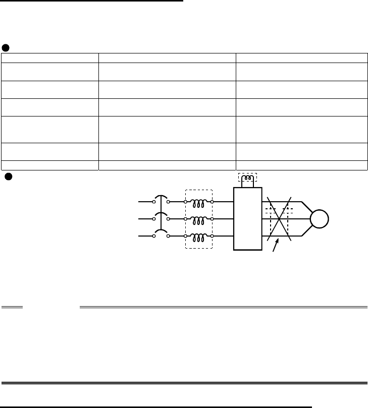
Suppression technique
Harmonic currents produced
on the power supply side by
the inverter change with such
conditions as whether there
are wiring impedances and a
power factor improving
reactor and the magnitudes of
output frequency and output
current on the load side.
Inverter
NFB
Power factor
improving AC reactor
Do not provide power factor
improving capacitor.
Power factor
improving DC reactor
Motor
IM
For the output frequency and output current, we understand that they should be
calculated in the conditions under the rated load at the maximum operating frequency.
CAUTION
The power factor improving capacitor and surge suppressor on the inverter output
side may be overheated or damaged by the harmonic components of the inverter
output. Also, since an excessive current flows in the inverter to activate overcurrent
protection, do not provide a capacitor and surge suppressor on the inverter output
side when the motor is driven by the inverter. To improve the power factor, insert a
power factor improving reactor in the inverter's primary side or DC circuit. For full
information, refer to page 18.
1
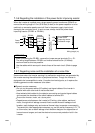
.5.10 Japanese power harmonic suppression guideline
Harmonic currents flow from the inverter to a power receiving point via a power
transformer. The harmonic suppression guideline was established to protect other
consumers from these outgoing harmonics.
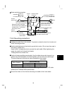
1) [Harmonic suppression guideline for household appliances and general-purpose
products]
The "harmonic suppression guideline for household appliances and general-purpose
products" issued by ex-Ministry of International Trade and Industry (present Ministry
of Economy, Trade and Industry) in September, 1994 applies to the FR-S500 series
other than the three-phase 400V class. By installing the FR-BEL or FR-BAL power
factor improving reactor, this product complies with the "harmonic suppression
techniques for transistorized inverters (input current 20A or less)" established by the
Japan Electrical Manufacturers' Association.