


53
2
Func-
tion
Calibra-
tion
parame-
ters
Indica-
tion
Name Setting Range
Minimum
Setting
Incre-
ments
Factory
Settin
g
Refer
To:
Cus-
tomer
Settin
g
<Japa-
nese>
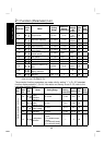
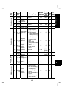
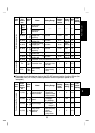
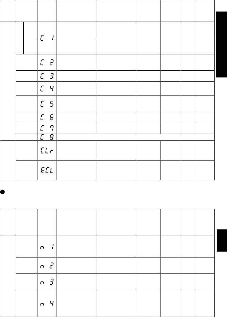
900
FM terminal
calibration
C1
<NA,
EC>
901
AM terminal
calibration
111
C2 (902)
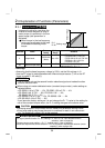
Frequency setting
voltage bias
frequency
0 to 60Hz 0.1Hz 0Hz 74
C3 (902)
Frequency setting
voltage bias
0 to 300% 0.1%
0%
(Note 2)
74
C4 (903)
Frequency setting
voltage gain
0 to 300% 0.1%
96%
(Note 2)
74
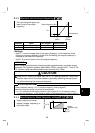
C5 (904)
Frequency setting
current bias
frequency
0 to 60Hz 0.1Hz 0Hz 74
C6 (904)
Frequency setting
current bias
0 to 300% 0.1%
20%
(Note 2)
74
C7 (905)
Frequency setting
current gain
0 to 300% 0.1%
100%
(Note 2)
74
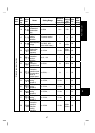
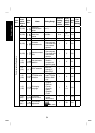
Calibration parameters
C8 (269) Parameter set by manufacturer. Do not set.
CLr Parameter clear
0: Not executed
1:
parameter clear
2: all clear
10115
Clear parameters
ECL *
Alarm history
clear
0: Not cleared,
1: Alarm history
clear
10115
Note 2: Settings may differ because of calibration parameters.
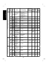
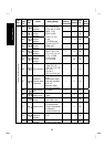
Parameters only for the type having the RS-485 communication function (When the
parameter unit (FR-PU04) is used, operation from the operation panel is not
accepted.)
Func-
tion
Com-
muni-
cation
Parame-
ter
Indica-
tion
Name Setting Range
Minimum
Setting
Incre-
ments
Factory
Settin
g
Refer
To:
Cus-
tomer
Settin
g
n1 (331)
Communication
station number
0 to 31:
Specify the
station number
of the inverter.
10118
n2 (332)
Communication
speed
48: 4800bps,
96: 9600bps,
192: 19200bps
1192118
n3 (333) Stop bit length
0, 1:
(Data length 8),
10, 11: (Data
length 7)
11118
Communication Parameters
n4 (334)
Parity check
presence/
absence
0: Absent,
1: With odd parity
check,
2: With even
parity check
12118
Pammeter List