


10
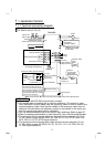
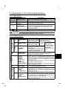
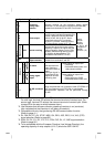
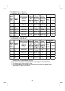
Symbol Terminal Name Description
Input signals
5
Frequency
setting input
common
Common terminal for the frequenc
y
settin
g
si
g
nals
(terminals 2, 4) and indicator connection (terminal AM).
Isolated from terminals SD and SE. Do not earth.
A
B
C
Alarm output
Change-over contact output indicating
that the output has been stopped by the
inverter's protective function activated.
230V 0.3A AC, 30V 0.3A DC. Alarm:
discontinuity across B-C (continuity
across A-C), normal: continuity across
B-C (discontinuity across A-C). (*6)
Open collector
RUN Inverter running
Switched low when the inverter output
frequency is equal to or higher than the
starting frequency (factory set to 0.5Hz,
variable). Switched high during stop or
DC injection brake operation. (*2)
Permissible load 24VDC 0.1A DC.
Output
terminal
function
selection
(Pr. 64, Pr. 65)
changes the
terminal
functions. (*5)
SE
Open collector
output common
Common terminal for inverter runnin
g
terminal RUN.
Isolated from terminals 5 and SD.
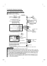
Pulse
FM
<Japanese>
For meter
Factory setting of output item:
Frequency
Permissible load current 1mA
1440 pulses/s at 60Hz
Output signals
Indicator
Analog
AM
<NA, EC>
Analog signal
output
One selected from
output frequency
and motor current is
output.
The output signal is
proportional to the
magnitude of each
monitoring item.
Factory setting of output item:
Frequency
Output signal 0 to 5VDC
Permissible load current 1mA
Communication
−−
−−−−
−−
RS-485 connector
(*3)
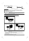
Usin
g
the parameter unit connection cable
(
FR-CB201 to
205), the parameter unit (FR-PU04) is connectable.
Communication operation can be performed throu
g
h
RS-485.
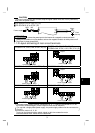
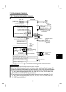
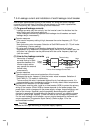
*1. Do not connect terminals SD and PC each other or to the earth.
For sink logic, terminal SD acts as the common terminal of contact input. For
source logic, terminal PC acts as the common terminal of contact input. (Refer
to page 25 for the way to switch between them.)
*2. Low indicates that the open collector outputting transistor is on (conducts).
High indicates that the transistor is off (does not conduct).
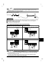
*3. Compatible with only the type having RS-485 communication function.
(Refer to page 41.)
*4. RL, RM, RH, RT, AU, STOP, MRS, OH, REX, JOG, RES, X14, X16, (STR)
signal selection (Refer to page 88.)
*5. RUN, SU, OL, FU, RY, Y12, Y13, FDN, FUP, RL, LF, ABC signal selection
(Refer to page 90.)
*6. To be compatible with the European Directive (Low Voltage Directive), the
operating capacity of relay outputs (A, B, C) should be 30V 0.3A DC.